
Technical Product Specification
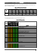
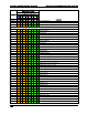

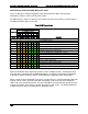
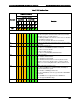


Table Of Contents
- 1. Introduction
- 2. Product Family Overview
- 3. Power Subsystem
- 3.1 Mechanical Overview
- 3.2 Power Connectors
- 3.3 Power Supply Module Efficiency
- 3.4 AC and DC Power Cord Specification Requirements
- 3.5 AC Input Specifications
- 3.5.1 Power Factor
- 3.5.2 AC Input Voltage Specification
- 3.5.3 AC Line Isolation Requirements
- 3.5.4 AC Line Dropout/Holdup
- 3.5.5 AC Line Fuse
- 3.5.6 AC Inrush
- 3.5.7 AC Line Transient Specification
- 3.5.8 Susceptibility Requirements
- 3.5.9 Electrostatic Discharge Susceptibility
- 3.5.10 Fast Transient/Burst
- 3.5.11 Radiated Immunity
- 3.5.12 Surge Immunity
- 3.5.13 Power Recovery
- 3.5.14 Voltage Interruptions
- 3.5.15 Protection Circuits
- 3.5.16 Over-current Protection (OCP)
- 3.5.17 Over-voltage Protection (OVP)
- 3.5.18 Over-temperature Protection (OTP)
- 3.6 1600W DC Power Supply Support
- 3.6.1 Power Supply Module Efficiency
- 3.6.2 DC Inlet Connector
- 3.6.3 DC Input Voltage Specification
- 3.6.4 DC Holdup/Dropout Time
- 3.6.5 DC Line Fuse
- 3.6.6 DC Inrush
- 3.6.7 DC Line Surge Voltages (Line Transients)
- 3.6.8 Residual Voltage Immunity in Standby Mode
- 3.6.9 Protection Circuits
- 3.6.10 Over Temperature Protection (OTP)
- 3.7 Cold Redundancy Support
- 3.8 Closed Loop System Throttling (CLST)
- 3.9 Smart Ride Through (SmaRT)
- 3.10 Power Supply Status LED
- 4. Thermal Management
- 5. System Storage and Peripheral Drive Bays Overview
- 6. Storage Controller Options Overview
- 7. Front Control Panel and I/O Panel Overview
- 8. Intel® Local Control Panel
- 9. PCI Riser Card Support
- 10. Additonal System Boards
- 11. Front Panel
- 12. IO Module Support
- 13. Intel® Intelligent Power Node Manager (NM)
- Appendix A: Integration and Usage Tip
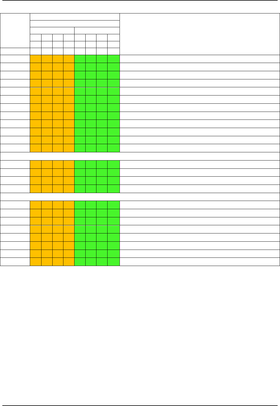
- Appendix B: POST Code Diagnostic LED Decoder
- Appendix C: POST Code Errors
- Glossary
- Reference Documents
Intel® Server System R2000LH2/T2 Product Family TPS Appendix B: POST Code Diagnostic LED Decoder
Revision 1.0
101
Checkpoint
Diagnostic LED Decoder
Description
1 = LED On, 0 = LED Off
Upper Nibble
Lower Nibble
MSB
LSB
8h
4h
2h
1h
8h
4h
2h
1h
LED #
#7
#6
#5
#4
#3
#2
#1
#0
ADh
1
0
1
0
1
1
0
1
DXE Ready to Boot
AEh
1
0
1
0
1
1
1
0
DXE Legacy Boot
AFh
1
0
1
0
1
1
1
1
DXE Exit Boot Services
B0h
1
0
1
1
0
0
0
0
RT Set Virtual Address Map Begin
B1h
1
0
1
1
0
0
0
1
RT Set Virtual Address Map End
B2h
1
0
1
1
0
0
1
0
DXE Legacy Option ROM init
B3h
1
0
1
1
0
0
1
1
DXE Reset system
B4h
1
0
1
1
0
1
0
0
DXE USB Hot plug
B5h
1
0
1
1
0
1
0
1
DXE PCI BUS Hot plug
B6h
1
0
1
1
0
1
1
0
DXE NVRAM cleanup
B7h
1
0
1
1
0
1
1
1
DXE Configuration Reset
00h
0
0
0
0
0
0
0
0
INT19
S3 Resume
E0h
1
1
0
1
0
0
0
0
S3 Resume PEIM (S3 started)
E1h
1
1
0
1
0
0
0
1
S3 Resume PEIM (S3 boot script)
E2h
1
1
0
1
0
0
1
0
S3 Resume PEIM (S3 Video Repost)
E3h
1
1
0
1
0
0
1
1
S3 Resume PEIM (S3 OS wake)
BIOS Recovery
F0h
1
1
1
1
0
0
0
0
PEIM which detected forced Recovery condition
F1h
1
1
1
1
0
0
0
1
PEIM which detected User Recovery condition
F2h
1
1
1
1
0
0
1
0
Recovery PEIM (Recovery started)
F3h
1
1
1
1
0
0
1
1
Recovery PEIM (Capsule found)
F4h
1
1
1
1
0
1
0
0
Recovery PEIM (Capsule loaded)
F8h
1
1
1
1
1
0
0
0
Recovery PPI not found
F9h
1
1
1
1
1
0
0
1
Recovery Capsule not found
FAh
1
1
1
1
1
0
1
0
Invalid Recovery Capsule