
Technical Product Specification
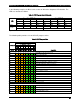
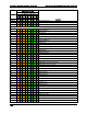

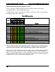
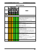


Table Of Contents
- 1. Introduction
- 2. Product Family Overview
- 3. Power Subsystem
- 3.1 Mechanical Overview
- 3.2 Power Connectors
- 3.3 Power Supply Module Efficiency
- 3.4 AC and DC Power Cord Specification Requirements
- 3.5 AC Input Specifications
- 3.5.1 Power Factor
- 3.5.2 AC Input Voltage Specification
- 3.5.3 AC Line Isolation Requirements
- 3.5.4 AC Line Dropout/Holdup
- 3.5.5 AC Line Fuse
- 3.5.6 AC Inrush
- 3.5.7 AC Line Transient Specification
- 3.5.8 Susceptibility Requirements
- 3.5.9 Electrostatic Discharge Susceptibility
- 3.5.10 Fast Transient/Burst
- 3.5.11 Radiated Immunity
- 3.5.12 Surge Immunity
- 3.5.13 Power Recovery
- 3.5.14 Voltage Interruptions
- 3.5.15 Protection Circuits
- 3.5.16 Over-current Protection (OCP)
- 3.5.17 Over-voltage Protection (OVP)
- 3.5.18 Over-temperature Protection (OTP)
- 3.6 1600W DC Power Supply Support
- 3.6.1 Power Supply Module Efficiency
- 3.6.2 DC Inlet Connector
- 3.6.3 DC Input Voltage Specification
- 3.6.4 DC Holdup/Dropout Time
- 3.6.5 DC Line Fuse
- 3.6.6 DC Inrush
- 3.6.7 DC Line Surge Voltages (Line Transients)
- 3.6.8 Residual Voltage Immunity in Standby Mode
- 3.6.9 Protection Circuits
- 3.6.10 Over Temperature Protection (OTP)
- 3.7 Cold Redundancy Support
- 3.8 Closed Loop System Throttling (CLST)
- 3.9 Smart Ride Through (SmaRT)
- 3.10 Power Supply Status LED
- 4. Thermal Management
- 5. System Storage and Peripheral Drive Bays Overview
- 6. Storage Controller Options Overview
- 7. Front Control Panel and I/O Panel Overview
- 8. Intel® Local Control Panel
- 9. PCI Riser Card Support
- 10. Additonal System Boards
- 11. Front Panel
- 12. IO Module Support
- 13. Intel® Intelligent Power Node Manager (NM)
- Appendix A: Integration and Usage Tip
- Appendix B: POST Code Diagnostic LED Decoder
- Appendix C: POST Code Errors
- Glossary
- Reference Documents
Intel® Server System R2000LH2/T2 Product Family TPS Appendix B: POST Code Diagnostic LED Decoder
Revision 1.0
99
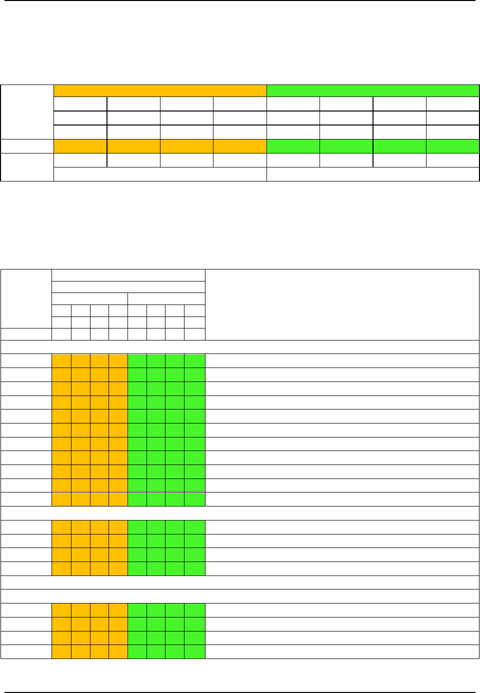
In the following example, the BIOS sends a value of ACh to the diagnostic LED decoder. The
LEDs are decoded as follows.
Table 44. POST Progress Code LED Example
LEDs
Upper Nibble AMBER LEDs
Lower Nibble GREEN LEDs
MSB
LSB
LED #7
LED #6
LED #5
LED #4
LED #3
LED #2
LED #1
LED #0
8h
4h
2h
1h
8h
4h
2h
1h
Status
ON
OFF
ON
OFF
ON
ON
OFF
OFF
Results
1
0
1
0
1
1
0
0
Ah
Ch
Upper nibble bits = 1010b = Ah; Lower nibble bits = 1100b = Ch; the two are concatenated as ACh
The following table provides a list of all POST progress codes..
Table 45. POST Progress Codes
Checkpoint
Diagnostic LED Decoder
Description
1 = LED On, 0 = LED Off
Upper Nibble
Lower Nibble
MSB
LSB
8h
4h
2h
1h
8h
4h
2h
1h
LED #
#7
#6
#5
#4
#3
#2
#1
#0
SEC Phase
01h
0
0
0
0
0
0
0
1
First POST code after CPU reset
02h
0
0
0
0
0
0
1
0
Microcode load begin
03h
0
0
0
0
0
0
1
1
CRAM initialization begin
04h
0
0
0
0
0
1
0
0
Pei Cache When Disabled
05h
0
0
0
0
0
1
0
1
SEC Core At Power On Begin.
06h
0
0
0
0
0
1
1
0
Early CPU initialization during Sec Phase.
07h
0
0
0
0
0
1
1
1
Early SB initialization during Sec Phase.
08h
0
0
0
0
1
0
0
0
Early NB initialization during Sec Phase.
09h
0
0
0
0
1
0
0
1
End Of Sec Phase.
0Eh
0
0
0
0
1
1
1
0
Microcode Not Found.
0Fh
0
0
0
0
1
1
1
1
Microcode Not Loaded.
PEI Phase
10h
0
0
0
1
0
0
0
0
PEI Core
11h
0
0
0
1
0
0
0
1
CPU PEIM
15h
0
0
0
1
0
1
0
1
NB PEIM
19h
0
0
0
1
1
0
0
1
SB PEIM
MRC Process Codes – MRC Progress Code Sequence is executed
PEI Phase continued…
31h
0
0
1
1
0
0
0
1
Memory Installed
32h
0
0
1
1
0
0
1
0
CPU PEIM (Cpu Init)
33h
0
0
1
1
0
0
1
1
CPU PEIM (Cache Init)
34h
0
0
1
1
0
1
0
0
CPU PEIM (BSP Select)