
Technical Product Specification
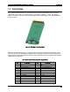

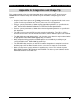
Table Of Contents
- 1. Introduction
- 2. Product Family Overview
- 3. Power Subsystem
- 3.1 Mechanical Overview
- 3.2 Power Connectors
- 3.3 Power Supply Module Efficiency
- 3.4 AC and DC Power Cord Specification Requirements
- 3.5 AC Input Specifications
- 3.5.1 Power Factor
- 3.5.2 AC Input Voltage Specification
- 3.5.3 AC Line Isolation Requirements
- 3.5.4 AC Line Dropout/Holdup
- 3.5.5 AC Line Fuse
- 3.5.6 AC Inrush
- 3.5.7 AC Line Transient Specification
- 3.5.8 Susceptibility Requirements
- 3.5.9 Electrostatic Discharge Susceptibility
- 3.5.10 Fast Transient/Burst
- 3.5.11 Radiated Immunity
- 3.5.12 Surge Immunity
- 3.5.13 Power Recovery
- 3.5.14 Voltage Interruptions
- 3.5.15 Protection Circuits
- 3.5.16 Over-current Protection (OCP)
- 3.5.17 Over-voltage Protection (OVP)
- 3.5.18 Over-temperature Protection (OTP)
- 3.6 1600W DC Power Supply Support
- 3.6.1 Power Supply Module Efficiency
- 3.6.2 DC Inlet Connector
- 3.6.3 DC Input Voltage Specification
- 3.6.4 DC Holdup/Dropout Time
- 3.6.5 DC Line Fuse
- 3.6.6 DC Inrush
- 3.6.7 DC Line Surge Voltages (Line Transients)
- 3.6.8 Residual Voltage Immunity in Standby Mode
- 3.6.9 Protection Circuits
- 3.6.10 Over Temperature Protection (OTP)
- 3.7 Cold Redundancy Support
- 3.8 Closed Loop System Throttling (CLST)
- 3.9 Smart Ride Through (SmaRT)
- 3.10 Power Supply Status LED
- 4. Thermal Management
- 5. System Storage and Peripheral Drive Bays Overview
- 6. Storage Controller Options Overview
- 7. Front Control Panel and I/O Panel Overview
- 8. Intel® Local Control Panel
- 9. PCI Riser Card Support
- 10. Additonal System Boards
- 11. Front Panel
- 12. IO Module Support
- 13. Intel® Intelligent Power Node Manager (NM)
- Appendix A: Integration and Usage Tip
- Appendix B: POST Code Diagnostic LED Decoder
- Appendix C: POST Code Errors
- Glossary
- Reference Documents
Appendix B: POST Code Diagnostic LED Decoder Intel® Server System R2000LH2/T2 Product Family TPS
Revision 1.0
98
Appendix B: POST Code Diagnostic LED Decoder
As an aid to assist in troubleshooting a system hang that occurs during a system’s Power-On
Self-Test (POST) process, the server board includes a bank of eight POST Code Diagnostic
LEDs on the back edge of the server board.
During the system boot process, Memory Reference Code (MRC) and System BIOS execute a
number of memory initialization and platform configuration processes, each of which is assigned
a specific hex POST code number. As each routine is started, the given POST code number is
displayed to the POST Code Diagnostic LEDs on the back edge of the server board.
During a POST system hang, the displayed post code can be used to identify the last POST
routine that was run prior to the error occurring, helping to isolate the possible cause of the hang
condition.
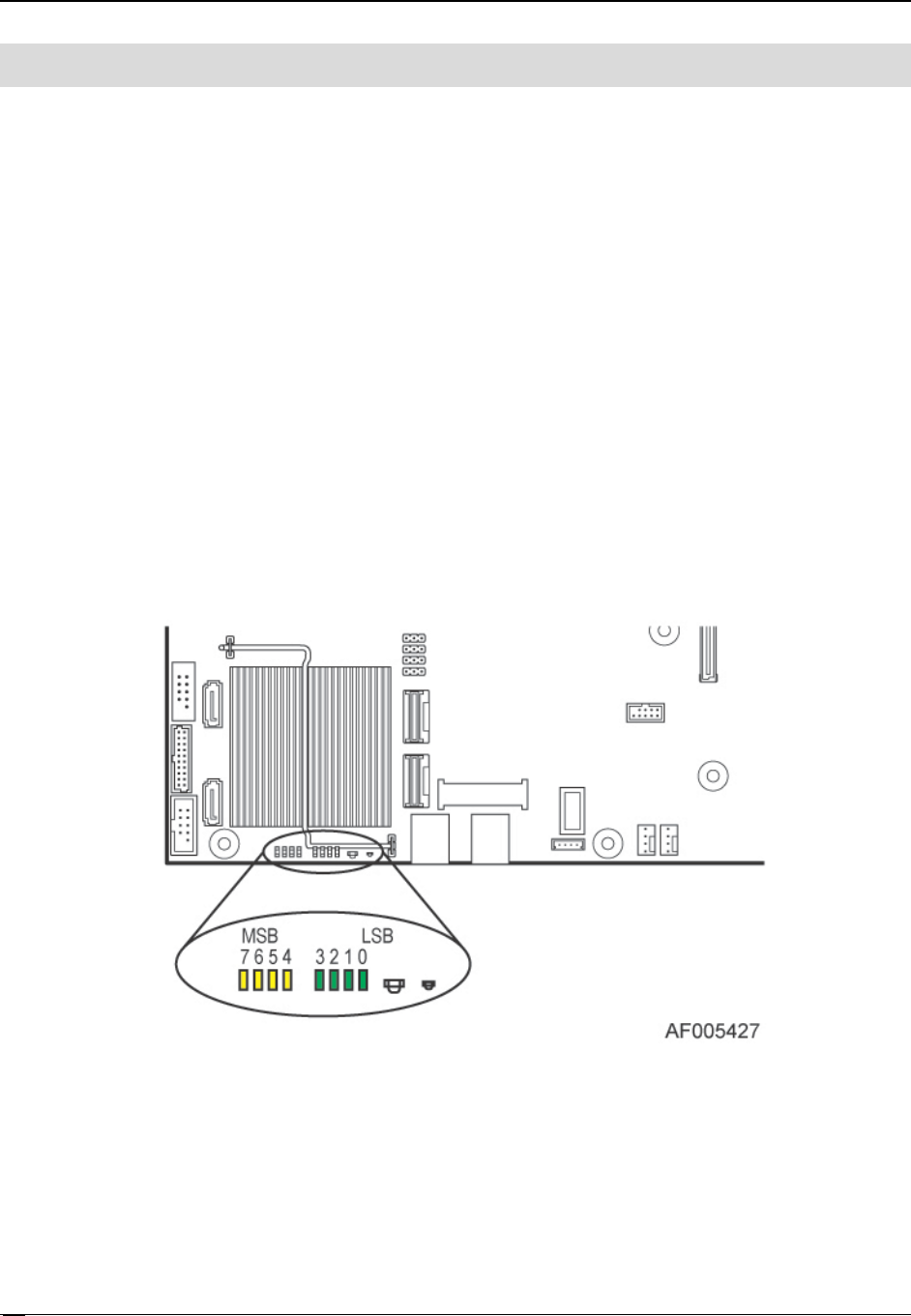
Each POST code is represented by eight LEDs; four Green and four Amber. The POST codes
are divided into two nibbles, an upper nibble and a lower nibble. The upper nibble bits are
represented by Amber Diagnostic LEDs #4, #5, #6, and #7. The lower nibble bits are
represented by Green Diagnostics LEDs #0, #1, #2, and #3. If the bit is set in the upper and
lower nibbles, the corresponding LED is lit. If the bit is clear, the corresponding LED is off.
Figure 79. POST Diagnostic LED Location