
Technical Product Specification
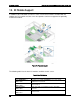
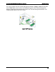

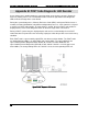
Table Of Contents
- 1. Introduction
- 2. Product Family Overview
- 3. Power Subsystem
- 3.1 Mechanical Overview
- 3.2 Power Connectors
- 3.3 Power Supply Module Efficiency
- 3.4 AC and DC Power Cord Specification Requirements
- 3.5 AC Input Specifications
- 3.5.1 Power Factor
- 3.5.2 AC Input Voltage Specification
- 3.5.3 AC Line Isolation Requirements
- 3.5.4 AC Line Dropout/Holdup
- 3.5.5 AC Line Fuse
- 3.5.6 AC Inrush
- 3.5.7 AC Line Transient Specification
- 3.5.8 Susceptibility Requirements
- 3.5.9 Electrostatic Discharge Susceptibility
- 3.5.10 Fast Transient/Burst
- 3.5.11 Radiated Immunity
- 3.5.12 Surge Immunity
- 3.5.13 Power Recovery
- 3.5.14 Voltage Interruptions
- 3.5.15 Protection Circuits
- 3.5.16 Over-current Protection (OCP)
- 3.5.17 Over-voltage Protection (OVP)
- 3.5.18 Over-temperature Protection (OTP)
- 3.6 1600W DC Power Supply Support
- 3.6.1 Power Supply Module Efficiency
- 3.6.2 DC Inlet Connector
- 3.6.3 DC Input Voltage Specification
- 3.6.4 DC Holdup/Dropout Time
- 3.6.5 DC Line Fuse
- 3.6.6 DC Inrush
- 3.6.7 DC Line Surge Voltages (Line Transients)
- 3.6.8 Residual Voltage Immunity in Standby Mode
- 3.6.9 Protection Circuits
- 3.6.10 Over Temperature Protection (OTP)
- 3.7 Cold Redundancy Support
- 3.8 Closed Loop System Throttling (CLST)
- 3.9 Smart Ride Through (SmaRT)
- 3.10 Power Supply Status LED
- 4. Thermal Management
- 5. System Storage and Peripheral Drive Bays Overview
- 6. Storage Controller Options Overview
- 7. Front Control Panel and I/O Panel Overview
- 8. Intel® Local Control Panel
- 9. PCI Riser Card Support
- 10. Additonal System Boards
- 11. Front Panel
- 12. IO Module Support
- 13. Intel® Intelligent Power Node Manager (NM)
- Appendix A: Integration and Usage Tip
- Appendix B: POST Code Diagnostic LED Decoder
- Appendix C: POST Code Errors
- Glossary
- Reference Documents
Intel® Intelligent Power Node Manager (NM) Intel® Server System R2000LH2/T2 Product Family TPS
Revision 1.0
94
13.1.4
ME System Management Bus (SMBus) Interface
The ME uses the SMLink0 on the SSB in multi-master mode as a dedicated bus for
communication with the BMC using the IPMB protocol. The EPSD BMC FW considers
this a secondary IPMB bus and runs at 400 kHz.
The ME uses the SMLink1 on the SSB in multi-master mode bus for communication with
PMBus devices in the power supplies for support of various NM-related features. This
bus is shared with the BMC, which polls these PMBus power supplies for sensor
monitoring purposes (for example, power supply status, input power, and so on). This
bus runs at 100 KHz.
The Management Engine has access to the Host SMBus.
13.1.5
PECI 3.0
The ME owns the PECI bus for all EPSD server implementations.
The ME uses SPI flash attached to the SSB to keep ME firmware code and configuration data.
This flash device is also used by system BIOS.
13.1.6
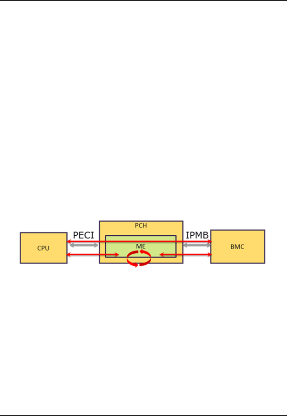
PECI Proxy
The PECI proxy feature is included for all Westerlee FW configurations.
The general concept is that PECI Proxy provides access to PECI interface for BMCs that do not
have direct PECI bus access.
Figure 78. PECI Proxy
PECI Proxy support includes the following:
Raw PECI: BMC can generate any PECI 3.0 network or link layer compatible transaction
by encapsulation in OEM IPMI commands. PECI transaction return information is
passed back to the BMC as an IPMI response. ME FW automatically retries PECI
transactions that completed with completion code that indicates that the operation has
started and that it has not completed yet.
Support for aggregating multiple PECI requests/responses in a single OEM IPMI
command.
Special IPMI Sensors representing data available over PECI.
Aggregated access to the CPU and memory temperature parameters over OEM IPMI
commands.