
Technical Product Specification
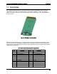

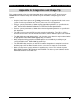
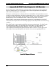
Table Of Contents
- 1. Introduction
- 2. Product Family Overview
- 3. Power Subsystem
- 3.1 Mechanical Overview
- 3.2 Power Connectors
- 3.3 Power Supply Module Efficiency
- 3.4 AC and DC Power Cord Specification Requirements
- 3.5 AC Input Specifications
- 3.5.1 Power Factor
- 3.5.2 AC Input Voltage Specification
- 3.5.3 AC Line Isolation Requirements
- 3.5.4 AC Line Dropout/Holdup
- 3.5.5 AC Line Fuse
- 3.5.6 AC Inrush
- 3.5.7 AC Line Transient Specification
- 3.5.8 Susceptibility Requirements
- 3.5.9 Electrostatic Discharge Susceptibility
- 3.5.10 Fast Transient/Burst
- 3.5.11 Radiated Immunity
- 3.5.12 Surge Immunity
- 3.5.13 Power Recovery
- 3.5.14 Voltage Interruptions
- 3.5.15 Protection Circuits
- 3.5.16 Over-current Protection (OCP)
- 3.5.17 Over-voltage Protection (OVP)
- 3.5.18 Over-temperature Protection (OTP)
- 3.6 1600W DC Power Supply Support
- 3.6.1 Power Supply Module Efficiency
- 3.6.2 DC Inlet Connector
- 3.6.3 DC Input Voltage Specification
- 3.6.4 DC Holdup/Dropout Time
- 3.6.5 DC Line Fuse
- 3.6.6 DC Inrush
- 3.6.7 DC Line Surge Voltages (Line Transients)
- 3.6.8 Residual Voltage Immunity in Standby Mode
- 3.6.9 Protection Circuits
- 3.6.10 Over Temperature Protection (OTP)
- 3.7 Cold Redundancy Support
- 3.8 Closed Loop System Throttling (CLST)
- 3.9 Smart Ride Through (SmaRT)
- 3.10 Power Supply Status LED
- 4. Thermal Management
- 5. System Storage and Peripheral Drive Bays Overview
- 6. Storage Controller Options Overview
- 7. Front Control Panel and I/O Panel Overview
- 8. Intel® Local Control Panel
- 9. PCI Riser Card Support
- 10. Additonal System Boards
- 11. Front Panel
- 12. IO Module Support
- 13. Intel® Intelligent Power Node Manager (NM)
- Appendix A: Integration and Usage Tip
- Appendix B: POST Code Diagnostic LED Decoder
- Appendix C: POST Code Errors
- Glossary
- Reference Documents
Intel® Server System R2000LH2/T2 Product Family TPS Front Panel
Revision 1.0
89
11. Front Panel
The common front panel feature set conforms to the industry standard SSI 2x12 connector
specification, but includes an extension to this connector to support 3
rd
and 4
th
NIC Activity
LEDs. The longer connector is a 2x15 right angle header, which includes missing pin locations
at pins 25 & 26.
Figure 75. SSI Common Front Panel Board
While the front panel board uses a custom 2x15 connector, the baseboard simply adds a 2x2
connector in-line (and appropriately spaced) with the existing SSI 2x12 connector. Boards that
support Quad LAN can populate the 2x2 connector, and boards that only support Dual LAN can
depopulate the connector.
Table 42. SSI Front Panel Connector Pin-out (Baseboard)
Pin #
SSI Sig name
Pin #
SSI Sig name
1
SB3.3V
2
SB3.3V
3
Key
4
SB5V
5
Power LED Cathode
6
System ID LED Cathode
7
3.3V
8
System Fault LED Anode
9
HDD Activity LED Cathode
10
System Fault LED Cathode
11
Power Switch
12
NIC#1 Activity LED
13
GND (Power Switch)
14
NIC#1 Link LED
15
Reset Switch
16
I2C SDA
17
GND (Reset/ID/NMI Switch)
18
I2C SCL
19
System ID Switch
20
Chassis Intrusion
21
Pull Down
22
NIC#2 Activity LED
23
NMI to CPU Switch
24
NIC#2 Link LED