
R2000GZ and R2000GL


Intel
®
Server System R2000GZ/GL Product Family TPS
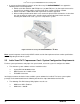
On the backside of each backplane are several connectors. The following illustration identifies each.
Label
Description
A
SMBus-Out cable connector for multi-backplane support
B
4-port Mini-SAS cable connectors
C
SMBus-In cable connector – From Server board or other backplane
D
Power connector
A and C – SMBus Cable Connectors – The backplane includes two 1x5 cable connectors used as a
management interface between the server board and the installed backplanes. In systems configured with
multiple backplanes, a short jumper cable is attached between backplanes, with connector B used on the first
board and connector D used on the second board, extending the SMBus to each installed backplane.
B – Multi-port Mini-SAS Cable Connectors – The backplane includes two multi-port mini-SAS cable
connectors, each providing SGPIO and I/O signals for four SAS/SATA storage devices on the backplane.
Cables can be routed from matching connectors on the server board, installed add-in SAS/SATA RAID cards,
or optionally installed SAS expander cards for drive configurations of greater than 8 storage devices.
D – Power Harness Connector – The backplane includes a 2x2 connector supplying power to the backplane.
Power is routed to each installed backplane via a multi-connector power cable harness from the server board.
6.1.2 Cypress* CY8C22545 Enclosure Management Controller
The backplanes support enclosure management using a Cypress* CY8C22545 Programmable System-on-
Chip (PSoC*) device.
The CY8C22545 drives the hard drive activity/fault LED, hard drive present signal, and
controls hard drive power-up during system power-on.
44 Revision 2.2