
S2600GZ and S2600GL


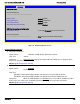


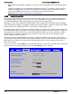


Table Of Contents
- 1. Introduction
- 2. Product Overview
- 3. Product Architecture Overview
- 3.1 Processor Support
- 3.2 Processor Functions Overview
- 3.2.1 Processor Core Features:
- 3.2.2 Supported Technologies:
- 3.2.3 Intel® QuickPath Interconnect
- 3.2.4 Integrated Memory Controller (IMC) and Memory Subsystem
- 3.2.4.1 Supported Memory
- 3.2.4.2 Memory Slot Identification and Population Rules
- 3.2.4.3 Publishing System Memory
- 3.2.4.4 Integrated Memory Controller Operating Modes
- 3.2.4.5 Memory RAS Support
- 3.2.5 Processor Integrated I/O Module (IIO)
- 3.3 Intel® C602 Chipset Functional Overview
- 3.4 Integrated Baseboard Management Controller Overview
- 4. System Security
- 5. Technology Support
- 6. Platform Management Functional Overview
- 6.1 Baseboard Management Controller (BMC) Firmware Feature Support
- 6.2 Advanced Configuration and Power Interface (ACPI)
- 6.3 Power Control Sources
- 6.4 BMC Watchdog
- 6.5 Fault Resilient Booting (FRB)
- 6.6 Sensor Monitoring
- 6.7 Field Replaceable Unit (FRU) Inventory Device
- 6.8 System Event Log (SEL)
- 6.9 System Fan Management
- 6.10 Messaging Interfaces
- 6.10.1 User Model
- 6.10.2 IPMB Communication Interface
- 6.10.3 LAN Interface
- 6.10.4 Address Resolution Protocol (ARP)
- 6.10.5 Internet Control Message Protocol (ICMP)
- 6.10.6 Virtual Local Area Network (VLAN)
- 6.10.7 Secure Shell (SSH)
- 6.10.8 Serial-over-LAN (SOL 2.0)
- 6.10.9 Platform Event Filter (PEF)
- 6.10.10 LAN Alerting
- 6.10.11 Alert Policy Table
- 6.10.12 SM-CLP (SM-CLP Lite)
- 6.10.13 Embedded Web Server
- 6.10.14 Virtual Front Panel
- 6.10.15 Embedded Platform Debug
- 6.10.16 Data Center Management Interface (DCMI)
- 6.10.17 Lightweight Directory Authentication Protocol (LDAP)
- 7. Advanced Management Feature Support (RMM4)
- 8. On-board Connector/Header Overview
- 9. Reset and Recovery Jumpers
- 10. Light Guided Diagnostics
- 11. Power Supply Specification Guidelines
- 11.1 Power Supply DC Output Connector
- 11.2 Power Supply DC Output Specification
- 11.2.1 Output Power/Currents
- 11.2.2 Standby Output
- 11.2.3 Voltage Regulation
- 11.2.4 Dynamic Loading
- 11.2.5 Capacitive Loading
- 11.2.6 Grounding
- 11.2.7 Closed loop stability
- 11.2.8 Residual Voltage Immunity in Standby mode
- 11.2.9 Common Mode Noise
- 11.2.10 Soft Starting
- 11.2.11 Zero Load Stability Requirements
- 11.2.12 Hot Swap Requirements
- 11.2.13 Forced Load Sharing
- 11.2.14 Ripple/Noise
- 11.2.15 Timing Requirements
- 12. BIOS Setup Utility
- Table 60. BIOS Setup: Keyboard Command Bar
- Back to [Main Screen]
- Back to [Main Screen]
- Back to [Main Screen]
- Back to [Main Screen]
- Back to [Main Screen]
- Back to [Main Screen]
- Back to [Main Screen]
- Back to [Main Screen]
- Back to [Advanced Screen]
- Back to [Advanced Screen]
- Back to [Advanced Screen]
- Back to [Advanced Screen]
- Back to [Advanced Screen]
- Back to [Advanced Screen]
- Back to [Advanced Screen]
- Back to [Advanced Screen]
- Screen Field Descriptions:
- Back to [Processor Configuration Screen] — [Advanced Screen]
- Back to [Processor Configuration Screen] — [Advanced Screen]
- Back to [Processor Configuration Screen] — [Advanced Screen]
- Back to [Processor Configuration Screen] — [Advanced Screen]
- Back to [Processor Configuration Screen] — [Advanced Screen]
- Back to [Processor Configuration Screen] — [Advanced Screen]
- Back to [Processor Configuration Screen] — [Advanced Screen]
- Back to [Processor Configuration Screen] — [Advanced Screen]
- Back to [Processor Configuration Screen] — [Advanced Screen]
- Back to [Processor Configuration Screen] — [Advanced Screen]
- Back to [Processor Configuration Screen] — [Advanced Screen]
- Back to [Processor Configuration Screen] — [Advanced Screen]
- Back to [Processor Configuration Screen] — [Advanced Screen]
- Back to [Processor Configuration Screen] — [Advanced Screen]
- Back to [Processor Configuration Screen] — [Advanced Screen]
- Back to [Processor Configuration Screen] — [Advanced Screen]
- Back to [Processor Configuration Screen] — [Advanced Screen]
- Back to [Processor Configuration Screen] — [Advanced Screen]
- Back to [Processor Configuration Screen] — [Advanced Screen]
- Back to [Processor Configuration Screen] — [Advanced Screen]
- Back to [Processor Configuration Screen] — [Advanced Screen]
- Back to [Processor Configuration Screen] — [Advanced Screen]
- Back to [Processor Configuration Screen] — [Advanced Screen]
- Back to [Processor Configuration Screen] — [Advanced Screen]
- Back to [Processor Configuration Screen] — [Advanced Screen]
- Back to [Processor Configuration Screen] — [Advanced Screen]
- Back to [Processor Configuration Screen] — [Advanced Screen]
- Back to Processor Configuration Screen] — [Advanced Screen]
- Back to [Processor Configuration Screen] — [Advanced Screen]
- Back to [Processor Configuration Screen] — [Advanced Screen]
- Back to [Processor Configuration Screen] — [Advanced Screen]
- Back to [Processor Configuration Screen] — [Advanced Screen]
- Back to [Processor Configuration Screen] — [Advanced Screen]
- Figure 44. Power & Performance Screen
- Back to [Power & Performance Screen] — [Advanced Screen]
- Figure 45. Memory Configuration Screen
- Back to [Memory Configuration Screen] — [Advanced Screen]
- Back to [Memory Configuration Screen] — [Advanced Screen]
- Back to [Memory Configuration Screen] — [Advanced Screen]
- Back to [Memory Configuration Screen] — [Advanced Screen]
- Back to [Memory Configuration Screen] — [Advanced Screen]
- Back to [Memory Configuration Screen] — [Advanced Screen]
- Back to [Memory Configuration Screen] — [Advanced Screen]
- Back to [Memory Configuration Screen] — [Advanced Screen]
- Back to [Memory Configuration Screen] — [Advanced Screen]
- Back to [Memory Configuration Screen] — [Advanced Screen]
- Back to [Memory Configuration Screen] — [Advanced Screen]
- Back to [Memory Configuration Screen] — [Advanced Screen]
- Back to [Memory Configuration Screen] — [Advanced Screen]
- Figure 46. Memory RAS and Performance Configuration Screen
- Figure 47. Mass Storage Controller Configuration Screen
- Screen Field Descriptions:
- One of these strings:
- Back to [Mass Storage Controller Configuration Screen]
- One of these strings:
- Back to [Mass Storage Controller Configuration Screen]
- Back to [Mass Storage Controller Configuration Screen]
- Back to [Mass Storage Controller Configuration Screen]
- Back to [Mass Storage Controller Configuration Screen]
- Back to [Mass Storage Controller Configuration Screen]
- Back to [Mass Storage Controller Configuration Screen]
- Back to [Mass Storage Controller Configuration Screen]
- Names of Storage Modules supported at this time are:
- Back to [Mass Storage Controller Configuration Screen]
- Back to [Mass Storage Controller Configuration Screen]
- Figure 48. PCI Configuration Screen
- Back to [PCI Configuration Screen] — [Advanced Screen]
- Back to [PCI Configuration Screen] — [Advanced Screen]
- Back to [PCI Configuration Screen] — [Advanced Screen]
- Back to [PCI Configuration Screen] — [Advanced Screen]
- Back to [PCI Configuration Screen] — [Advanced Screen]
- Back to [PCI Configuration Screen] — [Advanced Screen]
- Back to [PCI Configuration Screen] — [Advanced Screen]
- Figure 49. NIC Configuration Screen
- One of these strings:
- One of these strings:
- Figure 50. Serial Port Configuration Screen
- Back to [Serial Port Configuration Screen]
- Back to [Serial Port Configuration Screen]
- Back to [Serial Port Configuration Screen]
- Back to [Serial Port Configuration Screen]
- Back to [Serial Port Configuration Screen]
- Back to [Serial Port Configuration Screen]
- Figure 51. USB Configuration Screen
- Back to [USB Configuration Screen]
- Back to [USB Configuration Screen]
- Back to [USB Configuration Screen]
- Back to [USB Configuration Screen]
- Back to [USB Configuration Screen]
- Back to [USB Configuration Screen]
- Back to [USB Configuration Screen]
- Figure 52. System Acoustic and Performance Configuration
- Back to [System Acoustic and Performance Configuration]
- Back to [System Acoustic and Performance Configuration]
- Back to [System Acoustic and Performance Configuration]
- Back to [System Acoustic and Performance Configuration]
- Back to [System Acoustic and Performance Configuration]
- Figure 53. Security Screen
- Back to [Security Screen]
- Back to [Security Screen]
- Back to [Security Screen]
- Back to [Security Screen]
- Back to [Security Screen]
- Back to [Security Screen]
- Back to [Security Screen]
- Back to [Security Screen]
- Figure 54. Server Management Screen
- Back to [Server Management Screen]
- Back to [Server Management Screen]
- Back to [Server Management Screen]
- Back to [Server Management Screen]
- Back to [Server Management Screen]
- Back to [Server Management Screen]
- Back to [Server Management Screen]
- Back to [Server Management Screen]
- Back to [Server Management Screen]
- Back to [Server Management Screen]
- Back to [Server Management Screen]
- Back to [Server Management Screen]
- Back to [Server Management Screen]
- Back to [Server Management Screen]
- Back to [Server Management Screen]
- Back to [Server Management Screen]
- Back to [Server Management Screen]
- Back to [Server Management Screen]
- Back to [Server Management Screen]
- Back to [Server Management Screen]
- Figure 55. Console Redirection Screen
- Back to [Console Redirection Screen] — [Server Management Screen]
- Back to [Console Redirection Screen] — [Server Management Screen]
- Back to [Console Redirection Screen] — [Server Management Screen]
- Back to [Console Redirection Screen] — [Server Management Screen]
- Back to [Console Redirection Screen] — [Server Management Screen]
- Back to [Console Redirection Screen] — [Server Management Screen]
- Figure 56. System Information Screen
- Back to [System Information Screen] — [Server Management Screen]
- Back to [System Information Screen] — [Server Management Screen]
- Back to [System Information Screen] — [Server Management Screen]
- Back to [System Information Screen] — [Server Management Screen]
- Back to [System Information Screen] — [Server Management Screen]
- Back to [System Information Screen] — [Server Management Screen]
- Back to [System Information Screen] — [Server Management Screen]
- Back to [System Information Screen] — [Server Management Screen]
- Back to [System Information Screen] — [Server Management Screen]
- Back to [System Information Screen] — [Server Management Screen]
- Back to [System Information Screen] — [Server Management Screen]
- Figure 57. BMC LAN Configuration Screen
- Back to [BMC LAN Configuration Screen] — [Server Management Screen]
- Option Values: [Entry Field 0.0.0.0, 0.0.0.0 is default]
- Back to [BMC LAN Configuration Screen] — [Server Management Screen]
- Option Values: [Entry Field 0.0.0.0, 0.0.0.0 is default]
- Back to [BMC LAN Configuration Screen] — [Server Management Screen]
- Option Values: [Entry Field 0.0.0.0, 0.0.0.0 is default]
- Back to [BMC LAN Configuration Screen] — [Server Management Screen]
- Back to [BMC LAN Configuration Screen] — [Server Management Screen]
- Back to [BMC LAN Configuration Screen] — [Server Management Screen]
- Back to [BMC LAN Configuration Screen] — [Server Management Screen]
- Back to [BMC LAN Configuration Screen] — [Server Management Screen]
- Back to [BMC LAN Configuration Screen] — [Server Management Screen]
- Back to [BMC LAN Configuration Screen] — [Server Management Screen]
- Back to [BMC LAN Configuration Screen] — [Server Management Screen]
- Option Values: [Entry Field 0.0.0.0, 0.0.0.0 is default]
- Back to [BMC LAN Configuration Screen] — [Server Management Screen]
- Option Values: [Entry Field 0.0.0.0, 0.0.0.0 is default]
- Back to [BMC LAN Configuration Screen] — [Server Management Screen]
- Option Values: [Entry Field 0.0.0.0, 0.0.0.0 is default]
- Back to [BMC LAN Configuration Screen] — [Server Management Screen]
- Back to [BMC LAN Configuration Screen] — [Server Management Screen]
- Back to [BMC LAN Configuration Screen] — [Server Management Screen]
- Back to [BMC LAN Configuration Screen] — [Server Management Screen]
- Back to [BMC LAN Configuration Screen] — [Server Management Screen]
- Back to [BMC LAN Configuration Screen] — [Server Management Screen]
- Back to [BMC LAN Configuration Screen] — [Server Management Screen]
- Back to [BMC LAN Configuration Screen] — [Server Management Screen]
- Back to [BMC LAN Configuration Screen] — [Server Management Screen]
- Back to [BMC LAN Configuration Screen] — [Server Management Screen]
- Back to [BMC LAN Configuration Screen] — [Server Management Screen]
- Figure 58. Boot Options Screen
- Back to [Boot Options Screen]
- Back to [Boot Options Screen]
- Back to [Boot Options Screen]
- Back to [Boot Options Screen]
- Back to [Boot Options Screen]
- Back to [Boot Options Screen]
- Back to [Boot Options Screen]
- Back to [Boot Options Screen]
- Back to [Boot Options Screen]
- Back to [Boot Options Screen]
- Back to [Boot Options Screen]
- Back to [Boot Options Screen]
- Back to [Boot Options Screen]
- Back to [Boot Options Screen]
- Back to [Boot Options Screen]
- Back to [Boot Options Screen]
- Figure 59. CDROM Order Screen
- Back to [CDROM Order Screen] — [Boot Options Screen]
- Figure 60. Hard Disk Order Screen
- Back to [Hard Disk Order Screen] — [Boot Options Screen]
- Figure 61. Floppy Order Screen
- Back to [Floppy Order Screen] — [Boot Options Screen]
- Figure 62. Network Device Order Screen
- Back to [Network Device Order Screen] — [Boot Options Screen]
- Figure 63. BEV Device Order Screen
- Back to [BEV Device Order Screen] — [Boot Options Screen]
- Figure 64. Add EFI Boot Option Screen
- Figure 65. Delete EFI Boot Option Screen
- Figure 66. Boot Manager Screen
- Back to [Boot Manager Screen]
- Back to [Boot Manager Screen]
- Figure 67. Error Manager Screen
- Back to [Error Manager Screen]
- Back to [Error Manager Screen]
- Back to [Error Manager Screen]
- Back to [Error Manager Screen]
- Figure 68. Save & Exit Screen
- Back to [Save & Exit Screen]
- Back to [Save & Exit Screen]
- Back to [Save & Exit Screen]
- Back to [Save & Exit Screen]
- Back to [Save & Exit Screen]
- Back to [Save & Exit Screen]
- Back to [Save & Exit Screen]
- Appendix A: Integration and Usage Tips
- Appendix B: Integrated BMC Sensor Tables
- Appendix C: Management Engine Generated SEL Event Messages
- Appendix D: POST Code Diagnostic LED Decoder
- Appendix E: POST Code Errors
- Appendix F: Supported Intel® Server Systems

Intel® Server Board S2600GZ/GL TPS BIOS Setup Utility
2. Set Fan Profile
Option Values: Performance
Acoustic
Help Text:
[Performance] - Fan control provides primary system cooling before attempting to throttle
memory.
[Acoustic] - The system will favor using throttling of memory over boosting fans to cool the
system if thermal thresholds are met.
Comments: This option allows the user to choose a Fan Profile that is optimized for
maximizing performance or for minimizing acoustic noise.
When Performance is selected, the thermal conditions in the system are controlled by raising fan speed
when necessary to raise cooling performance. This provides cooling without impacting system
performance, but may impact system acoustic performance – fans running faster are typically louder.
The Performance mode is designed to provide sufficient cooling capability covering all kinds of add-in
cards on the market.
When Acoustic is selected, then rather than increasing fan speed for additional cooling, the system will
attempt first to control thermal conditions by throttling memory to reduce heat production. This regulates
the system’s thermal condition without changing the acoustic performance, but throttling memory may
impact system performance. The Acoustic mode offers best acoustic experience and appropriate
cooling capability covering mainstream and majority of the add-in cards.
The BMC only supports enabling a fan profile through the command if that profile is supported on all fan
domains defined for the given system. It is important to configure platform Sensor Data Records
(SDRs) so that all desired fan profiles are supported on each fan domain. If no single profile is
supported across all domains, the BMC, by default, uses profile 0 and does not allow it to be changed.
Back to [System Acoustic and Performance Configuration
]
3. Fan PWM Offset
Option Values: [Entry Field 0 – 100, 0 is default]
Help Text:
Valid Offset 0 - 100. This number is added to the calculated PWM value to increase Fan Speed.
Comments: This is a percentage by which the calculated fan speed will be increased. The
user can apply positive offsets that result in increasing the minimum fan speeds. This feature is valid
when Quiet Fan Idle Mode is at Enabled state.
Back to [System Acoustic and Performance Configuration
]
4. Quiet Fan Idle Mode
Option Values: Enabled
Disabled
Help Text:
Enabling this option allows the system fans to operate in Quiet ‘Fan off’ mode while still
maintaining sufficient system cooling. In this mode, fan sensors become unavailable and cannot
be monitored. There will be limited fan related event generation.
Comments: When enabled, this option allows fans to idle or turn off when sufficient thermal
margin is available, decreasing the acoustic noise produced by the system and decreasing system
power consumption. Fans will run as needed to maintain thermal control. The actual decrease in fan
speed depends on the system thermal loading, which in turn depends on system configuration and
workload.
Revision 2.4
153