
R2000GZ and R2000GL


Intel
®
Server System R2000GZ/GL Product Family TPS
With a 2-slot riser card installed, the embedded fan speed control will operate system fans at a higher
speed. 3-slot riser cards (as shipped in the standard platform configuration) cannot be used due to
air flow and thermal limitations.
NOTE: The latest posted system software updates must be installed on the system to ensure proper fan speed
control is enabled. The latest system update package can be downloaded from the following Intel web site:
http://downloadcenter.intel.com.
• High power add-in cards with active cooling solutions that require up to 300W, can be supported. A
total system power budget should be calculated to determine if the power draw of the desired system
configuration meets the power limits of the installed power supplies. A power budget tool for the
specified system can be downloaded from http://www.intel.com/support.
• Riser cards can support a maximum combined (all PCIe slots) power draw of up to 75W. Add-in cards
with power requirements above 75W will require the additional power to be drawn from either of two
2x2 pin “OPT_12V_ PWR” connectors on the server board. See section 3.2.2 Riser Card Power
Connectors, for the Optional12V power connector usage and power cable specification. Power cables
for these connectors are included in the A2UL16RISER accessory kit and can support both 6 and 8 pin
12V AUX power connectors located on the add-in cards.
• Configuration Note: In order to support a GPGPU card in Riser Slot #1, the Auxiliary 12V power
connector of the add-in card MUST be located on the back edge of the card. Aux 12V power
connectors located on the top edge of the add-in card will interfere with the chassis side wall.
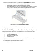
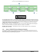
5.2 Using High Power Add-in Cards with Passive Cooling Solutions
• Due to air flow and thermal limitations, high power add-in cards with passive cooling solutions will only
be supported in the following base system SKUs: R2308GZ##### and R2208GZ#####, and only
when configured with the contents included in the Intel Accessory Kit – AGZCOPRODUCT. This
accessory kit includes the following: new air duct design, two 2-slot PCIe riser cards, two 12V Auxiliary
power cables. See Appendix D at the end of this document for additional configuration information.
NOTE: Due to thermal and air flow limitations, High power add-in cards (> 75W) with passive heat sinks
cannot be supported in systems configured with the standard (default) air duct or the 3-slot PCIe riser cards
that are included in the standard shipping configuration.
NOTE: Intel Accessory Kit AGZCOPRODUCT is NOT compatible with any of the Intel
®
Server System
R2000GL product family. (System integrated with the 16-DIMM Intel
®
Server Board S2600GL).
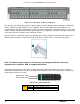
• High power add-in cards with passive cooling solutions that require up to 300W, can be supported. A
total system power budget should be calculated to determine if the power draw of the desired system
configuration meets the power limits of the installed power supplies. A power budget tool for the
specified system can be downloaded from http://www.intel.com/support.
• Riser cards can support a maximum combined (all PCIe slots) power draw of up to 75W. Add-in cards
with power requirements above 75W will require the additional power to be drawn from either of the
two 2x2 pin “OPT_12V_ PWR” connectors on the server board. Power cables for these connectors are
included in the A2UL16RISER accessory kit and can support both 6 and 8 pin 12V AUX power
connectors located on the add-in cards. See section 3.2.2 Riser Card Power Connectors, for the
Optional12V power connector usage and power cable specification.
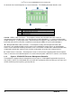
• Configuration Note: In order to support a GPGPU card in Riser Slot #1, the Auxiliary 12V power
connector of the add-in card MUST be located on the back edge of the card. Aux 12V power
connectors located on the top edge of the add-in card will interfere with the chassis side wall.
Revision 2.2
39