
R2000GZ and R2000GL


Intel
®
Server System R2000GZ/GL Product Family TPS
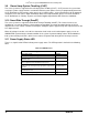
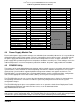
System Configuration - 16x 2.5” hard drive bay or 8x 3.5” hard drive bay configuration + Intel
®
Server Board S2600GZ (24 DIMM server board)
Memory slot 3 populated on all memory channels
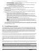
System Configuration - 24x 2.5” hard drive bay or 12x 3.5” hard drive bay configuration +
Intel
®
Server Board S2600GL (16 DIMM server board)
Memory slot 2 populated on all memory channels
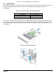
• All hard drive bays must be populated. Hard drive carriers can be populated with a hard drive or
supplied drive blank.
• With the system operating, the air duct must be installed at all times
• In single power supply configurations, the 2
nd
power supply bay must have the supplied filler blank
installed at all times.
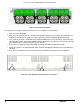
• The system must be configured with dual power supplies for the system to support fan redundancy.
• Thermally, the system can support the following PCI add-in cards.
o Add-in cards with a minimum 100 LFM (0.5 m/s) air flow requirement can be installed in any
available add-in card slot in both Riser Card #1 and Riser Card #2
o Add-in cards with a minimum 200 LFM (1 m/s) air flow requirement can be installed in any
available add-in card slot on Riser Card #2 and the bottom add-in card slot on Riser Card #1.
Middle and Top add-in card slots on Riser Card #1 cannot support PCI add-in cards with air flow
requirements greater than 100 LFM.
o Add-in cards with a >200 LFM air flow requirement cannot be supported.
o Note: Most PCI add-in cards have minimum air flow requirements of 100 LFM (0.5m/s). Some
high power add-in cards have minimum air flow requirements of 200 LFM (1 m/s). System
integrators should verify PCI add-in card air flow requirements from vendor specifications when
integrating add-in cards into the system.
• The system top-cover must be installed at all times when the system is in operation. The only exception
to this requirement is to hot replace a failed system fan, in which case the top cover can be removed for
no more than 3 minutes at a time
4.2 Thermal Management Overview
In order to maintain the necessary airflow within the system, all of the previously listed components and top
cover need to be properly installed.
For best system performance, the external ambient temperature should
remain below 35ºC and all system fans should be operational. The system is designed for fan redundancy
when the system is configured with two power supplies. Should a single system fan fail (System fan or Power
Supply Fan), integrated platform management will: change the state of the System Status LED to flashing
Green, report an error to the system event log, and automatically adjust fan speeds as needed to maintain
system temperatures below maximum thermal limits.
Note: All system fans are controlled independent of each other. The fan control system may adjust fan speeds
for different fans based on increasing/decreasing temperatures in different thermal zones within the chassis.
In the event that system temperatures should continue to increase with the system fans operating at their
maximum speed, platform management may begin to throttle bandwidth of either the memory subsystem or
the processors or both, in order to keep components from overheating and keep the system operational.
Throttling of these sub-systems will continue until system temperatures are reduced below preprogrammed
limits.
Should system thermals increase to a point beyond the maximum thermal limits, the system will shut down, the
System Status LED will change to a solid Amber state, and the event will be logged to the system event log.
Note: Sensor data records (SDRs) for any given system configuration must be loaded by the system integrator
for proper thermal management of the system. SDRs are loaded using the FRUSDR utility.
An intelligent Fan Speed Control (FSC) and thermal management technology (mechanism) is used to maintain
comprehensive thermal protection, deliver the best system acoustics, and fan power efficiency. Options in <F2>
32 Revision 2.2