
R2000GZ and R2000GL


Intel
®
Server System R2000GZ/GL Product Family TPS
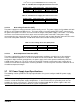
3.7.8.1 Current Limit (OCP)
The power supply shall have current limit to prevent the outputs from exceeding the values shown in table
below. If the current limits are exceeded the power supply shall shutdown and latch off. The latch will be
cleared by toggling the PSON# signal or by an DC power interruption. The power supply shall not be damaged
from repeated power cycling in this condition. 12VSB will be auto-recovered after removing OCP limit.
Table 21. Over Current Protection
Output
VOLTAGE
Input voltage
range
OVER CURRENT LIMITS
+12V
72A min; 78A max
12VSB
2.5A min; 3.5A max
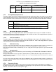
3.7.8.2 Over Voltage Protection (OVP)
The power supply over voltage protection shall be locally sensed. The power supply shall shutdown and latch
off after an over voltage condition occurs. This latch shall be cleared by toggling the PSON# signal or by an
DC power interruption. The values are measured at the output of the power supply’s connectors. The voltage
shall never exceed the maximum levels when measured at the power connectors of the power supply
connector during any single point of fail. The voltage shall never trip any lower than the minimum levels when
measured at the power connector. 12VSBwill be auto-recovered after removing OVP limit.
Table 22. Over Voltagge Protection Limits
Output Voltage
MIN (V)
MAX (V)
+12V
13.3
14.5
+12VSB
13.3
14.5
3.7.8.3 Over Temperature Protection (OTP)
The power supply will be protected against over temperature conditions caused by loss of fan cooling or
excessive ambient temperature. In an OTP condition the PSU will shutdown. When the power supply
temperature drops to within specified limits, the power supply shall restore power automatically, while the
12VSB remains always on. The OTP circuit must have built in margin such that the power supply will not
oscillate on and off due to temperature recovering condition. The OTP trip level shall have a minimum of 4 C
of ambient temperature margin
3.8 Cold Redundancy Support
Power supplies that support cold redundancy can be enabled to go into a low-power state (that is, cold
redundant state) in order to provide increased power usage efficiency when system loads are such that both
power supplies are not needed. When the power subsystem is in Cold Redundant mode, only the needed
power supply to support the best power delivery efficiency is ON. Any additional power supplies; including the
redundant power supply, is in Cold Standby state
Each power supply has an additional signal that is dedicated to supporting Cold Redundancy; CR_BUS. This
signal is a common bus between all power supplies in the system. CR_BUS is asserted when there is a fault in
any power supply OR the power supplies output voltage falls below the Vfault threshold. Asserting the
CR_BUS signal causes all power supplies in Cold Standby state to power ON.
Enabling power supplies to maintain best efficiency is achieved by looking at the Load Share bus voltage and
comparing it to a programmed voltage level via a PMBus command.
Whenever there is no active power supply on the Cold Redundancy bus driving a HIGH level on the bus all
power supplies are ON no matter their defined Cold Redundant roll (active or Cold Standby). This guarantees
that incorrect programming of the Cold Redundancy states of the power supply will never cause the power
28 Revision 2.2