
Quick Installation User's Guide


8
General Installation Process
14
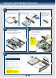
Install Rack Handles
NOTE: Rack handles are required to install the bezel.
For detailed instructions, see the product Service
Guide available on the Intel
®
Server Deployment &
Management DVD.
13
Install Add-in Card Riser Assembly
Position the riser card edge
connector over the server
board riser socket and align
the two hooks of the riser with
the slots at the back of the
chassis, then press straight
down into riser socket.
NOTE:
A 2
nd
CPU must be
installed to support the x16 PCIe
slot when installing a supporting
x16 Riser card.
Add-in Card
Slots (2)
Hooks (2)
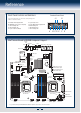
15
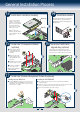
Install Intel® I/O Expansion Module
(optional)
A
D
B
Squeeze the sides of the I/O
module bay filler plate, and
pull it away from the chassis
back panel.
Fit the front of the module
into the back panel slot and
align the I/O Module over the
3 stand-offs.
Secure the module with the
three screws as shown.
C
Carefully press down on the I/O
module to engage connectors.
NOTE: If included, remember to
install the EMI shield.
I/O Connector
I/O Module
A
B
C
D
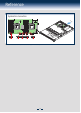
16
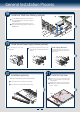
Install Intel® RAID C600
Upgrade Key (optional)
Locate the white 4-pin key header next to Riser Slot 2.
Carefully pickup the Intel
®
RAID C600 Upgrade Key. Match
the Key and connector orientation and press down to install.
STOR_UPG_KEY
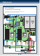
17
Install Intel® Remote Management Module 4 (optional)
A
Locate the RMM4 Lite connector close to the Riser Slot 2,
carefully pickup the Intel
®
RMM4 Lite module, match the
alignment pin of the module and the connector on server
board, then press to install.
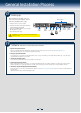
Installing the Intel® RMM4 Lite
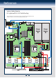
Push out and remove the metal cover on the chassis where the NIC RJ-45
receptacle will align.
A
Position the module over the server board, fit the front of the module into the back
panel slot, then attach the module to the server board connector.
B
Secure the module with the two screws as shown.
C
Installing the Intel® RMM4 NIC
RMM4 Lite
Connector
A
Chassis Back
Opening
Filler
A
B
C