
Intel Server Board S2400BB


Intel® Server Board S2400BB TPS
Revision 2.0
80
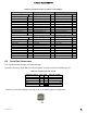
Table 40. Serial A Connector Pin-out
Signal Description
Pin#
RTS
1
DTR
2
SOUT
3
GROUND
4
RI
5
SIN
6
DCD or DSR
7**
CTS
8
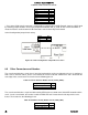
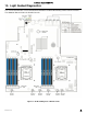
** Pin 7 of the RJ45 Serial A connector is configurable to support either a DSR (Default) signal or a DCD signal
by switching jumper locations on the 3-pin jumper block labeled “SRL_A_CFG” on the server board which is
located next to the stacked external USB connectors near the back edge of the board.
Serial-A configuration jumper block setting:
Signal
Pins
DSR (Default)
1-2
DCD
2-3
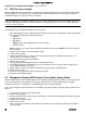
8.6 Other Connectors and Headers
The server board includes a 2-pin chassis intrusion header which can be used when the chassis is configured
with a chassis intrusion switch. On the server board, this header is labeled “CHAS INTR” and is located on the
front edge of the server board. The header has the following pin-out.
Table 41. Chassis Intrusion Header Pin-out ("CHAS_INTR")
Signal Description
Pin#
FP_CHASSIS_INTRUSION
1
GROUND
2
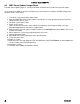
The server board includes a 2-pin hard drive activity LED header used with some SAS/SATA controller add-in
cards. On the server board, this header is labeled “HDD LED” and is located on the left edge of the server
board. The header has the following pin-out.
Table 42. Hard Drive Activity Header Pin-out ("HDD_LED")
Signal Description
Pin#
LED_HDD_ACT_N
1
TP_LED_HDD_ACT
2
Figure 29. Serial A Configuration Jumper Block Location