
Intel Server Board S2400BB


Intel® Server Board S2400BB TPS
Revision 2.0
28
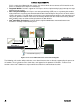
Each Ethernet port drives two LEDs located on each network interface connector. The LED at the right of the
connector is the link/activity LED and indicates network connection when on, and transmit/receive activity when
blinking. The LED at the left of the connector indicates link speed as defined in the following table.
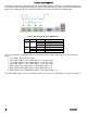
Table 9. External RJ45 NIC Port LED Definition
LED
Color
LED State
NIC State
Left Green
Off
LAN link not established
On
LAN link is established
Blinking
LAN activity is occurring
Right
Off
10 Mb/sec data rate
Amber
On
100 Mb/sec data rate
Green
On
1000 Mb /sec data rate
The server board has seven MAC addresses programmed at the factory. MAC addresses are assigned as
follows:
• NIC 1 MAC address (for OS usage)
• NIC 2 MAC address = NIC 1 MAC address + 1 (for OS usage)
• NIC 3 MAC address = NIC 1 MAC address + 2 (for OS usage)
• NIC 4 MAC address = NIC 1 MAC address + 3 (for OS usage)
• BMC LAN channel 1 MAC address = NIC1 MAC address + 4
• BMC LAN channel 2 MAC address = NIC1 MAC address + 5
• BMC LAN channel 3 (RMM) MAC address = NIC1 MAC address + 6
The printed MAC address on the server board and/or server system is assigned to NIC1 on the server board.