
Intel Server Board S2400BB


Intel® Server Board S2400BB TPS
Revision 2.0
19
set to support all DIMMs populated (i.e, DIMMs with slower timings will force faster DIMMs to the slower
common timing modes).
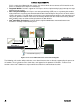
Figure 11. Memory Channel Pairing for RAS Support
3.2.2.4.1 Independent Channel Mode
In x4 SDDC configurations, each channel is running independently (nonlock-step), that is, each cache-line from
memory is provided by a channel. To deliver the 64-byte cache-line of data, each channel is bursting eight 8-
byte chunks. Back to back data transfer in the same direction and within the same rank can be sent back-to-
back without any dead-cycle. The independent channel mode is the recommended method to deliver most
efficient power and bandwidth as long as the x8 SDDC is not required.
3.2.2.4.2 Lockstep Channel Mode
In lockstep channel mode, the cache-line is split across channels. This is done to support Single Device Data
Correction (SDDC) for DRAM devices with 8-bit wide data ports. Also, the same address is used on both
channels, such that an address error on any channel is detectable by bad ECC. The iMC module always
accumulates 32-bytes before forwarding data so there is no latency benefit for disabling ECC.
Lockstep channels must be populated identically. That is, each DIMM in one channel must have a
corresponding DIMM of identical organization (number ranks, number banks, number rows, number columns).
DIMMs may be of different speed grades, but the iMC module will be configured to operate all DIMMs
according to the slowest parameters present by the Memory Reference Code (MRC).
Performance in lockstep mode cannot be as high as with independent channels. The burst length for DDR3
DIMMs is eight which is shared between two channels that are in lockstep mode. Each channel of the pair
provides 32 bytes to produce the 64-byte cache-line. DRAMs on independent channels are configured to
deliver a burst length of eight. The maximum read bandwidth for a given Rank is half of peak. There is another
draw back in using lockstep mode, i.e. higher power consumption since the total activation power is about
twice of the independent channel operation if comparing to same type of DIMMs.
3.2.2.5 Mirrored Channel Mode
Channel Mirroring Mode gives the best memory RAS capability by maintaining two copies of the data in main
memory. If there is an Uncorrectable ECC Error, the channel with the error is disabled and the system
continues with the “good” channel, but in a non-redundant configuration.
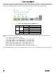
For Mirroring mode to be to be available as a RAS option, the DIMM population must be identical between
each pair of memory channels that participate. Not all channel pairs need to have memory installed, but for
each pair, the configuration must match. If the configuration is not matched up properly, the memory operating
mode falls back to Independent Channel Mode.
Mirroring Mode is enabled/disabled in the Memory RAS and Performance Configuration screen in the <F2>
BIOS Setup Utility.
A
B
C
D
E
F
Lockstep
or
Mirrored
Pair
Lockstep
or
Mirrored
Pair