Intel® Server System R1000BB Family Quick Installation User's Guide Thank you for buying an Intel® Server System. The following information will help you assemble your Intel® Server System and install components. If you are not familiar with ESD [Electrostatic Discharge] procedures used during system integration, see the complete ESD procedures described in your Service Guide. This guide and other supporting documents are located on the web at: http://www.intel.com/support. * 2.
( This page is intentionally left blank.
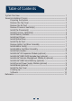
Table of Contents System Overview .............................................................................................................................. 1 General Installation Process ........................................................................................................ 2 Preparing the System ...................................................................................................... 2 Remove the Top Cover ..................................................................
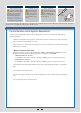
Warning Warning Caution Read all caution and safety statements in this document before performing any of the instructions. Also see the Intel ® Server Board and Server Chassis Safety Information document at: http://www.intel.com/support/ motherboards/server/sb/cs-010770 .htm for complete safety information. Installation and service of this product to be performed only by qualified service personnel to avoid risk of injury from electrical shock or energy hazard.
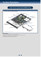
System Overview Intel® Server System R1000BB Family System Features and Components PCI Riser #2 Server Board CPU2 Memory Slots PCI Riser #1 Power Supply #1 Power Supply CPU2 System Fans #2 CPU1 Hot Swap Hard Drive Bays CPU1 Memory Slots Air Duct Front Control Panel * 2.5" Hard Drive Bay system as shown Useful Information: • See product Technical Product Specification for supported riser slot configurations.
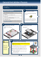
General Installation Process The installation instructions in this section are for common components of Intel® Server System R1000BB family. 1 Minimum Hardware Requirements To avoid integration difficulties and possible board damage, your system must meet the following minimum requirements: • Processor: Intel® Xeon® processor E5-2400 product family. Preparing the System Observe normal ESD (Electrostatic Discharge) procedures.
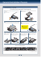
General Installation Process 5 Install the Processor(s) Cautions: A. Open the Socket Lever 1. When opening a socket, DO NOT TOUCH the gold socket wires. B. Open the Load Plate A Push the lever handle down and away from the socket to release it. B Rotate the lever open all the way. A A Push the rear tab with your finger tip to bring the front end of the load plate up slightly. Take the processor out of the box and remove the protective shipping cover. A NO CPU A B NO 2.
General Installation Process 6 CAUTION: Do not over-tighten fasteners. CAUTION: The heatsink has thermal interface material (TIM) on the underside of it. Use caution so that you do not damage the thermal interface material. Use gloves to avoid sharp edges. A Remove the protective film on the TIM if present. B Align heatsink fins to the front and back of the chassis for correct airflow. Airflow goes from front-to-back of chassis.
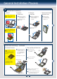
General Installation Process Install Memory Modules ... Continued To Install DIMMs: Open both DIMM socket levers. C Insert DIMM making sure the connector edge of the DIMM aligns correctly with the slot. D Push down firmly on the DIMM until it snaps into place and both levers close. E IMPORTANT! Visually check that each latch is fully closed and correctly engaged with each DIMM edge slot. C E CAUTION: Avoid touching contacts when handling or installing DIMMs. A B Note location of alignment notch.
General Installation Process Install Hard Drives ... Continued 3.5" Hard Drive Carrier (For system with 3.5" hard drive bay only) Remove the drive carrier by pressing the green button and opening the lever. B Slide the carrier out. TO P C Remove the four screws securing the plastic drive blank and remove the plastic drive blank. TO P BRE 2.5´´BEFOR AK OF HAR E MO F TAB D D UTIN RIV G E B AB NG F T TI E OF OU IV K M DR EA RE RD BR EFO HA B 5´´ 2.
General Installation Process 9 A Install Optical Drive Install the plastic guide onto the back of the drive and attach with two screws as shown. B C Insert the optical drive into chassis opening and push all the way until it stops. Connect the cables as shown. cal OptiDrive A IMPORTANT NOTE: If you do not install a device at this location, install the optical device bay filler panel shown below. This is required to maintain proper system cooling.
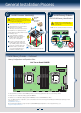
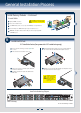
General Installation Process 13 14 Install Add-in Card Riser Assembly Hooks (2) Position the riser card edge connector over the server board riser socket and align the two hooks of the riser with the slots at the back of the chassis, then press straight down into riser socket. NOTE: Rack handles are required to install the bezel. For detailed instructions, see the product Service Guide available on the Intel® Server Deployment & Management DVD.
General Installation Process 18 Install Intel® RAID Smart Battery (optional) A Locate the BBU bracket inside the chassis. Align the tabs on the plastic battery holder with mounting holes on the BBU bracket. B Slide the plastic battery holder toward the rear of the system until the tabs engage with the mounting holes in the BBU bracket. A B 19 A Install Second Power Supply Module (optional) Use the 'finger hole' to remove the filler panel.
General Installation Process 22 Finishing Up Before installing your operating system, you must finish your system installation, make I/O connections, and plug in power cord(s). Add-in Card Slots 1. Verify the system top cover is installed. 2. Install the server into the rack using the instructions provided with the rack mounting kit. 3. Connect your USB keyboard/mouse, video and other I/O cables/devices as shown. Then connect the power cord(s).
Reference Front Panel Controls and Indicators Standard Control Panel Your system may include one of two front control panel types.The features of each are as follows: A. ID Button with integrated LED B. NMI Button (recessed, tool required) C. LAN-1 Activity LED D. LAN-3 Activity LED E. System Cold Reset Button J I H B C D E F F. System Status LED G. Power Button with integrated LED H. HDD Activity LED I. LAN-4 Activity LED J.
Reference System Fan Connection Air F 1 CPU2 Socket 2 CPU1 Socket 3 4 5 FAN 1 FAN 2 FAN 3 FAN 4 FAN 5 A complete list of accessories and spares can be found at: http://www.intel.com/support.
Reference System Cabling Diagram For system with 8 x 2.5” hard drive bay: Note: To activate the port SCU1 (4-7) on the server board, a proper Intel® RAID C600 Upgrade Key must be installed. For instructions, see Intel® RAID C600 Upgrade Key Installation Guide. 0 1 PCIe RAID Install in available PCIe add-in card slot I2C Power Supply #1 HSBP_I2C Power Supply #2 mSATA SSD Integrated BMC FAN 3 FAN 4 FAN 5 8 x 2.
Reference System Cabling Diagram For system with 4 x 3.5” hard drive bay: Note: To activate the port SCU1 (4-7) on the server board, a proper Intel® RAID C600 Upgrade Key must be installed. For instructions, see Intel® RAID C600 Upgrade Key Installation Guide. 0 1 PCIe RAID Install in available PCIe add-in card slot I2C Power Supply #1 HSBP_I2C Power Supply #2 mSATA SSD Integrated BMC Integrated BMC FAN 4 4 x 3.
( This page is intentionally left blank.
G48799-002