
Technical Product Specification

Appendix B: POST Code LED Decoder IntelP
®
P Server System R1000JP Family TPS
Appendix B: POST Code LED Decoder
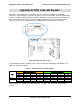
During the system boot process, the BIOS executes a number of platform configuration
processes, each of which is assigned a specific hex POST code number. As each configuration
routine is started, the BIOS displays the POST code to the POST Code Diagnostic LEDs on the
back edge of the server board. To assist in troubleshooting a system hang during the POST
process, you can use the diagnostic LEDs to identify the last POST process executed.
Figure 64. Diagnostic LED location
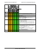
In the following example, the BIOS sends a value of ACh to the diagnostic LED decoder. The
LEDs are decoded as follows:
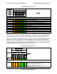
Table 41. POST Progress Code LED Example
LEDs
Upper Nibble AMBER LEDs
Lower Nibble GREEN LEDs
MSB
LSB
LED #7
LED #6
LED #5
LED #4
LED #3
LED #2
LED #1
LED #0
8h
4h
2h
1h
8h
4h
2h
1h
Status
ON
OFF
ON
OFF
ON
ON
OFF
OFF
Results
1
0
1
0
1
1
0
0
Ah
Ch
Upper nibble bits = 1010b = Ah; Lower nibble bits = 1100b = Ch; the two are concatenated
as ACh.
Revision 1.7 69
Intel
order number: G71652-008