
Technical Product Specification

Intel
®
Local Control Panel IntelP
®
P Server System R1000JP Family TPS
5. Any further Left or Right buttons will decrement or increment the value at that position.
6. Second Enter button at that position makes the cursor to be ready for moving left or right.
Any further Left or Right moves the cursor to previous or next position respectively.
7. So, the Enter button is used to select a position at the first time and to leave the position
at the second time.
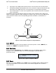
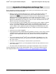
The following state transition diagram explains the above steps pictorially, while setting an IP
address using the LCD device. After entering an IP address, the user has to select “Set” item to
set the entered IP address to the corresponding parameter (IP Address, Subnet Mask, or
Gateway).
Figure 55. State transition diagram for setting IP Address
8.5.3 RMM4 IP
Same screen shots and the same description as that of the previous section (“BMC IP”) are
applicable for “RMM4 IP” configuration menu also.
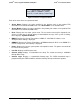
8.5.4 Boot Device
If the user selects “Boot Device” in the “Config” menu, then the following options will be
displayed. The selected item will be set as the next boot option and it will not be a
permanent change.
Figure 56. Boot options Configuration Menu
8.5.5 Banner
When the user selects “Banner” in the “Config” menu, the following options will be displayed.
The selected item will be set as banner and the same will be displayed from next banner
screen onwards.
^ | CD\DVD | Hard Drive | Network
Boot | EFI Shell
Left/
Right
Enter
Enter
Left
Left
Right
Right
Pos:
x
Pos:
x+1
Pos:
x-1
Increment/
Decrement
Revision 1.7 61
Intel
order number: G71652-008