
Technical Product Specification

Front Control Panel and I/O Panel Overview IntelP
®
P Server System R1000JP Family TPS
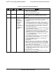
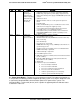
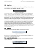
Color
State
Criticality
Description
Amber
~1 Hz blink
Non-critical -
System is
operating in a
degraded state
with an impending
failure warning,
although still
functioning
Non-fatal alarm – system is likely to fail:
1. Critical threshold crossed – Voltage, temperature (including
HSBP temp), input power to power supply, output current for
main power rail from power supply, and PROCHOT (Therm Ctrl)
sensors.
2. VRD Hot asserted.
3. Minimum number of fans to cool the system not present or
failed.
4. Hard drive fault.
5. Power Unit Redundancy sensor – Insufficient resources offset
(indicates not enough power supplies present).
6. In non-sparing and non-mirroring mode if the threshold of
correctable errors is crossed within the window.
7. Correctable memory error threshold has been reached for a
failing DDR3 DIMM when the system is operating in a non-
redundant mode.
Amber
Solid on
Critical, non-
recoverable –
System is halted
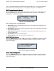
Fatal alarm – system has failed or shutdown:
1. CPU CATERR signal asserted.
2. MSID mismatch detected (CATERR also asserts for this case).
3. CPU 1 is missing.
4. CPU Thermal Trip.
5. No power good – power fault.
6. DIMM failure when there is only 1 DIMM present and hence no
good memory present
1
.
7. Runtime memory uncorrectable error in non-redundant mode.
8. DIMM Thermal Trip or equivalent.
9. SSB Thermal Trip or equivalent.
10. CPU ERR2 signal asserted.
11. BMC\Video memory test failed. (Chassis ID shows blue/solid-on
for this condition).
12. Both uBoot BMC FW images are bad. (Chassis ID shows
blue/solid-on for this condition).
13. 240VA fault.
14. Fatal Error in processor initialization:
a. Processor family not identical.
b. Processor model not identical.
c. Processor core/thread counts not identical.
d. Processor cache size not identical.
e. Unable to synchronize processor frequency.
f. Unable to synchronize QPI link frequency.
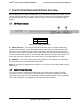
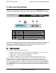
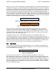
G – Power/Sleep Button – Toggles the system power on and off. This button also functions as
a sleep button if enabled by an ACPI compliant operating system. Pressing this button will send
a signal to the Integrated BMC, which will either power on or power off the system. The
integrated LED is a single color (Green) and is capable of supporting different indicator states
as defined in Table 39.
Revision 1.7 53
Intel
order number: G71652-008