
Technical Product Specification

IntelP
®P
Server System R1000JP FamilyTPS Front Control Panel and I/O Panel Overview
7 Front Control Panel and I/O Panel Overview
On the front panel of all system configurations is a Control Panel providing push button system
controls and LED indicators for several system features, and an I/O Panel providing USB ports
and a video connector. This section describes the features and functions of both front panel
options.
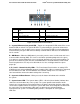
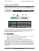
7.1 I/O Panel Features
Label
Description
A
Video connector
B
USB ports
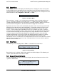
Figure 36. Front I/O Panel Features
A – Video connector – The front I/O Panel video connector gives the option of attaching a
monitor to the front of the system. When BIOS detects that a monitor is attached to the front
video connector, it disables the video signals routed to the on-board video connector on the
back of the system. Video resolutions from the front video connector may be lower than that of
the rear on-board video connector. A short video cable should be used for best resolution. The
front video connector is cabled to a 2x7 header on the server board labeled “FP Video”.
B – USB Ports – The front I/O panel includes two USB ports. The USB ports are cabled to a
2x5 connector on the server board labeled “FP USB”.
Note: On systems that support 8x2.5” hard drives, the I/O Panel can be replaced with a SATA
optical drive.
7.2 Control Panel Features
The system includes a control panel that provides push button system controls and LED
indicators for several system features. Depending on the hard drive configuration, the front
control panel may come in either of two formats; however, both provide the same functionality.
This section will provide a description for each front control panel feature.
Revision 1.7
Intel
order number: G71652-008
50