
Technical Product Specification

IntelP
®P
Server System R1000JP Family TPS System Storage and Peripheral Options
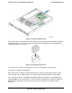
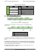
5.2.1 3.5” Drive Hot-Swap Backplane Overview
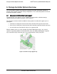
On the front side of each back plane are mounted four hard disk drive interface connectors (A),
each providing both power and I/O signals to attached hard disk drives.
Figure 32. The front side of 4 x 3.5” Hotswap Backplane
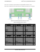
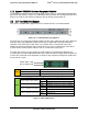
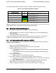
On the backside of each backplane are several connectors. The following illustration
identifies each.
Label
Description
A
7-pin SATA/SAS I/O connectors
B
SMBus*-In cable connector – From Server board
C
SGPIO connector
D
Power connector
Figure 33. The back side of 4 x 3.5” Hotswap Backplane
A – 7-pin SATA I/O Connectors – The backplane has four 7-pin SATA/SAS I/O connectors, one
for each hard drive. A single multi-connector cable is routed from the backplane to a four port
mini-SAS connector on the server board or other optionally installed SATA/SAS host bus
adapter.
B – SMBus* Cable Connectors – The backplane includes a 1x5 cable connector used as a
management interface to the server board.
C – SGPIO Cable Connector – The SGPIO connector is a management interface used to
control the hard drive fault LEDs on the backplane. The SGPIO signals are routed through a
multi-connectors cable that is routed to a four port mini-SAS connector on the server board or
other optionally installed SATA/SAS host bus adapter.
D – Power Harness Connector - The backplane includes a 2x2 connector supplying power to
the backplane. Power is routed to the backplane through a power cable harness from the server
board.
Revision 1.7 45
Intel
order number: G71652-008