
Technical Product Specification

System Storage and Peripheral Options IntelP
®P
Server System R1000JP Family TPS
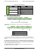
5.1.2 Cypress* CY8C22545 Enclosure Management Controller
The backplane supports enclosure management using a Cypress* CY8C22545 Programmable
System-on-Chip (PSoC*) device.
The CY8C22545 drives the hard drive activity/fault LED, hard
drive present signal, and controls hard drive power-up during system power-on.
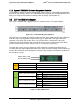
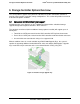
5.2 3.5” Hard Disk Drive Support
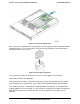
The server is available with support for four 3.5” hard disk drives as illustrated below.
Figure 30. 3.5" Hard Drive Bay Configuration
The drive bay can support either SATA or SAS hard disk drives. Mixing of drive types within the
hard drive bay is not supported. Hard disk drive type is dependent on the type of host bus
controller used, SATA only or SAS. Each 3.5” hard disk drive is mounted to a drive tray,
allowing for hot swap extraction and insertion. Drive trays have a latching mechanism that is
used to extract and insert drives from the chassis, and lock the tray in place.
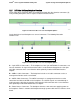
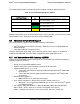
The hard drive carrier can also support 2.5” SSD. Light pipes integrated into the drive tray
assembly direct the light emitted from Amber drive status and Green activity LEDs located next
to each drive connector on the backplane, to the drive tray faceplate, making them visible from
the front of the system.
Amber
Off
No access and no fault
Solid On
Hard Drive Fault has occured
Blink
RAID rebuild in progress (1 Hz), Identify (2 Hz)
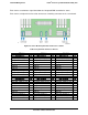
Figure 31. LED of HDD Carrier
Green
Condition
Drive Type
Behavior
Power on with no drive activity
SAS
LED stays on
SATA
LED stays off
Power on with drive activity
SAS
LED blinks off when processing a command
SATA
LED blinks on when processing a command
Power on and drive spun down
SAS
LED stays off
SATA
LED stays off
Power on and drive spinning up
SAS
LED blinks
SATA
LED stays off
Amber Status LED
Green Activity LED
Revision 1.7
Intel
order number: G71652-008
44