
Technical Product Specification

Thermal Management IntelP
®
P Server System R1000JP Family TPS
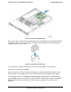
Each fan has a tachometer signal that allows the integrated BMC to monitor its status.
Each fan has a10-pin wire harness that connects to a matching connector on the server board.
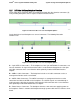
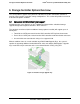
Figure 25. Server Board System Fan Connector Locations
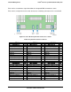
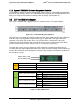
Table 34. System Fan Connector Pin-out
SYS_FAN 1
SYS_FAN 2
SYS_FAN 3
Signal Description
Pin#
Signal Description
Pin#
Signal Description
Pin#
FAN_TACH1_IN
1
FAN_TACH3_IN
1
FAN_TACH5_IN
1
FAN_IBMC_PWM0_R_BUF
2
FAN_IBMC_PWM1_R_BUF
2
FAN_IBMC_PWM2_R_BUF
2
P12V_FAN
3
P12V_FAN
3
P12V_FAN
3
P12V_FAN
4
P12V_FAN
4
P12V_FAN
4
FAN_TACH0_IN
5
FAN_TACH2_IN
5
FAN_TACH4_IN
5
GROUND
6
GROUND
6
GROUND
6
GROUND
7
GROUND
7
GROUND
7
FAN_SYS0_PRSNT_N
8
FAN_SYS1_PRSNT_N
8
FAN_SYS2_PRSNT_N
8
LED_FAN_FAULT0_R
9
LED_FAN_FAULT1_R
9
LED_FAN_FAULT2_R
9
LED_FAN0
10
LED_FAN1
10
LED_FAN2
10
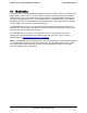
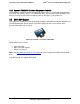
SYS_FAN 4
SYS_FAN 5
SYS_Fan 6 (not used)
Signal Description
Pin#
Signal Description
Pin#
Signal Description
Pin#
FAN_TACH7_IN
1
FAN_TACH9_IN
1
FAN_TACH11_IN
1
FAN_IBMC_PWM3_R_BUF
2
FAN_IBMC_PWM4_R_BUF
2
FAN_IBMC_PWM5_R_BUF
2
P12V_FAN
3
P12V_FAN
3
P12V_FAN
3
P12V_FAN
4
P12V_FAN
4
P12V_FAN
4
FAN_TACH6_IN
5
FAN_TACH8_IN
5
FAN_TACH10_IN
5
GROUND
6
GROUND
6
GROUND
6
GROUND
7
GROUND
7
GROUND
7
FAN_SYS3_PRSNT_N
8
FAN_SYS4_PRSNT_N
8
FAN_SYS5_PRSNT_N
8
LED_FAN_FAULT3_R
9
LED_FAN_FAULT4_R
9
LED_FAN_FAULT5_R
9
LED_FAN3
10
LED_FAN4
10
LED_FAN5
10
Revision 1.7
Intel
order number: G71652-008
40