
Technical Product Specification

Thermal Management IntelP
®
P Server System R1000JP Family TPS
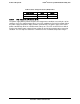
On-board Ethernet Controller Temperature Sensors
3, 5
Add-In Intel
®
SAS/IO Module Temperature Sensors
3, 5
PSU Thermal Sensor
3, 8
CPU VR Temperature Sensors
3, 6
DIMM VR Temperature Sensors
3, 6
BMC Temperature Sensor
3, 6
Global Aggregate Thermal Margin Sensors
7
I/O module Temperature Sensor (With option installed)
Intel
®
ROC Module (With option installed)
Notes:
1. For fan speed control in Intel
®
chassis
2. Temperature margin from throttling threshold
3. Absolute temperature
4. PECI value or margin value
5. On-die sensor
6. On-board sensor
7. Virtual sensor
8. Available only when PSU has PMBus*
9. Calculated estimate
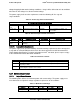
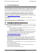
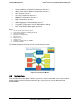
The following diagram illustrates the fan speed control structure:
Figure 22. Fan Control Model
4.3 System Fans
Four managed dual rotor 40mm x 56mm system fans and an embedded fan for each installed
power supply, provide the primary airflow for the system (five fans for R1304JP4GS and
R1208JP4GS).
Revision 1.7
Intel
order number: G71652-008
38