
Technical Product Specification


Appendix D: POST Code LED Decoder Intel® Server Board S1600JP TPS
Appendix D: POST Code LED Decoder
During the system boot process, the BIOS executes several platform configuration processes,
each of which is assigned a specific hex POST code number. As each configuration routine is
started, the BIOS displays the POST code on the POST code diagnostic LEDs found on the
back edge of the server board. To assist in troubleshooting a system hang during the POST
process, the diagnostic LEDs can be used to identify the last denote POST process to be
executed.
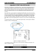
Each POST code is represented by the eight diagnostic LEDs which can be found on the back
edge of the server board and form a 2 hex digit (8 bit) code read left-to-right as facing the rear of
the server. The POST codes are divided into two nibbles, an upper nibble and a lower nibble.
The upper nibble bits are represented by diagnostic LEDs #4, #5, #6, and #7. The lower nibble
bits are represented by diagnostics LEDs #0, #1, #2, and #3. If the bit is set in the upper and
lower nibbles, then the corresponding LED is lit. If the bit is clear, then the corresponding LED is
off.
The diagnostic LED #7 is labeled as “MSB” (Most Significant Bit), and the diagnostic LED #0 is
labeled as “LSB” (Least Significant Bit).
Figure 56. Post Diagnostic LED Location
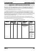
In the following example, the BIOS sends a value of ACh to the diagnostic LED decoder. The
LEDs are decoded as follows:
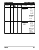
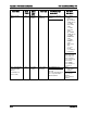
Table 99. POST Progress Code LED Example
LEDs
Upper Nibble LEDs
Lower Nibble LEDs
216 Revision 1.9