
Technical Product Specification

Intel® Server Board S1600JP TPS Connector/Header Locations and Pin-out
7.3.13
SSI Front Panel Header
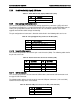
The server board provides one front panel header (J6H1) to support the standard Scythe pin-out
is defined in the following table and so on.
Table 78. SSI Front Panel Header Pin-Out (J6H1)
Pin
SSI Signal name
Pin
SSI Signal Name
1
SB3.3V
2
SB3.3V
3
Key
4
SB5V
5
Power LED Cathode
6
System ID LED Cathode
7
3.3V
8
System Fault LED Anode
9
HDD Activity LED Cathode
10
System Fault LED Cathode
11
Power Switch
12
NIC#1 Activity LED
13
GND (Power Switch)
14
NIC#1 Link LED
15
Reset Switch
16
I
2
C SDA
17
GND (Reset/ID/NMI Switch)
18
I
2
C SCL
19
System ID Switch
20
Chassis Intrusion
21
Pull Down
22
NIC#2 Activity LED
23
NMI to CPU Switch
24
NIC#2 Link LED
1
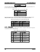
NIC#3 Activity LED
2
NIC#4 Activity LED
3
NIC#3 Link LED
4
NIC#4 Link LED
7.3.14
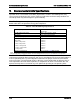
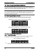
SMB PMBus* Connector
The server board provides one SMB PMBus* Connector (J6H2). The pin-out is defined in the
following table and so on.
Table 79. PMBus* Connector Pin-Out (J6H2)
Pin
Signal Name
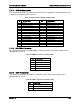
1 SMB_PWR_CLK
2
SMB_PWR_DAT
3
SMB_PWR_ALRT
4 GND
5
3.3V RS
7.3.15
HSBP I
2
C Connector
The server board provides one HSBP I
2
C connector (J1E2). The pin-out is defined in the
following table and so on.
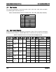
Table 80. HSBP I
2
C Connector Pin-Out (J1E2)
Pin
Signal Name
1
SMB_HSBP_3V3STBY_DATA
2
GND
3
SMB_HSBP_3V3STBY_CLK
Revision 1.9 169