
Technical Product Specification

Intel® Server Board S1600JP TPS Connector/Header Locations and Pin-out
7.3.8
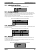
Hard Drive Activity (Input) LED Header
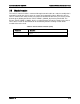
Table 71. SATA HDD Activity (Input) LED Header (J6F1)
Pin
Description
1
LED_HD_ACTIVE_L
2
NC
7.3.9
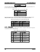
Storage Upgrade Key Connector
The server board provides one SATA/SAS storage upgrade key connector (J3E1) on board.
The Storage Upgrade Key is a small PCB board that has up to two security EEPROMs that are
read by the system ME to enable different versions of LSI* RAID 5 software stack and/or
upgrade from SATA to SAS storage functionality.
The pin configuration of connector is identical and defined in the following table and so on.
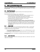
Table 72. Storage Upgrade Key Connector Pin-Out (J3E1)
Pin
Signal Description
1
GND
2
FM_PBG_DYN_SKU_KEY_R
3
GND
4
FM_SSB_SAS_SATA_RAID_KEY_R
7.3.10
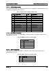
Serial Port Connectors
The server board provides one internal 9-pin serial A header (J5A2). The following tables define
the pin-outs and so on.
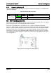
Table 73. Internal Serial Port Connecter Pin-Out (J5A2)
Pin
Signal Name
Pin
Signal Name
1
SPA_DCD
2
SPA_DSR
3
SPA_SIN_N
4
SPA_RTS
5
SPA_SOUT_N
6
SPA_CTS
7
SPA_DTR
8
SPA_RI
9
GND
7.3.11
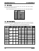
USB Connectors
The server board provides one two external USB headers, two internal USB connectors and
one type A USB connector.
The following table defines the pin-out of the external USB port connectors (J1A1 and J2A1)
found on the back edge of the server board.
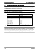
Table 74. External USB port Connector Pin-Out (J1A1 and J2A1)
Pin
Signal Name
1
P5V_AUX
2
USB2_Px_REAR_DN
3
USB2_Px_REAR_DP
Revision 1.9 167