
Technical Product Specification

Intel® Server Board S1600JP TPS Connector/Header Locations and Pin-out
7.2.8
Chassis ID LED
The chassis ID LED provides a visual indication of a system being serviced. The state of the
chassis ID LED is affected by the following:
Toggled by the chassis ID button
Controlled by the Chassis Identify command (IPMI)
Controlled by the Chassis Identify LED command (OEM)
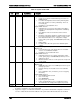
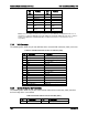
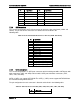
Table 61. Chassis ID LED Indicator States
State
LED State
Identify active through button
Solid on
Identify active through command
~1 Hz blink
Off
Off
There is no precedence or lock-out mechanism for the control sources. When a new request
arrives, all previous requests are terminated. For example, if the chassis ID LED is blinking and
the chassis ID button is pressed, then the chassis ID LED changes to solid on. If the button is
pressed again with no intervening commands, the chassis ID LED turns off.
7.3
I/O Connectors
7.3.1
PCI Express* Connectors
The Intel
®
Server Board S1600JP uses three PCI Express* slots physically with different pint out
definition. Each riser slot has dedicated usage and cannot be used for normal PCIe based add-
in card.
Riser Slot 1: Riser to support PCIe x16 add-in card
Riser Slot 2: Riser to support PCIe x8 Intel
®
IOM card
Riser Slot 3: Riser to support PCIe x16 add-in card or double width PCI Express* card
The pin-outs for the slots are shown in the following tables.
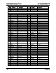
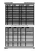
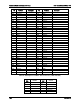
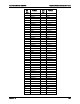
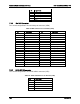
Table 62. PCI Express* x16 Riser Slot 1 Connector (J6B1)
Pin
Pin Name
Description
Pin
Pin Name
Description
B1 12V 66W for double width
PCI Express*card
A1 Present1
B2
12V
66W for double width
PCI Express*card
A2
12V
66W for double width PCI
Express*card
B3
12V
66W for double width
PCI Express*card
A3
12V
66W for double width PCI
Express*card
B4
GND
A4
GND
B5
SMBUS_R4
CLK
A5
3.3V
B6
SMBUS_R4
DAT
For wake on LAN
A6
spare
B7
GND
A7
spare
B8
3.3V
A8
3.3V
Revision 1.9 159