
Technical Product Specification
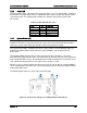

Intel® Server Board S1600JP TPS Connector/Header Locations and Pin-out
7.2.6
Power LED
The green power LED is active when the system DC power is on. The power LED is controlled
by the BIOS. The power LED reflects a combination of the state of system (DC) power and the
system ACPI state. The following table identifies the different states that the power LED
can assume.
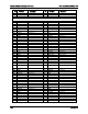
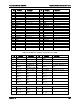
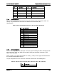
Table 59. Power LED Indicator States
State
ACPI
Power LED
Power off
No
Off
Power on
No
Solid on
S5
Yes
Off
S1 Sleep
Yes
~1 Hz blink
S0
Yes
Solid on
7.2.7
System Status LED
Note: The system status LED state shows the state for the current, most severe fault. For
example, if there was a critical fault due to one source and a non-critical fault due to another
source, the system status LED state would be solid on (the critical fault state).
The system status LED is a bicolor LED. Green (status) shows a normal operation state or a
degraded operation. Amber (fault) shows the system hardware state and overrides the
green status.
The Integrated BMC-detected state and the state from the other controllers, such as the
SCSI/SATA hot-swap controller state, are included in the LED state. For fault states monitored
by the Integrated BMC sensors, the contribution to the LED state follows the associated sensor
state, with the priority going to the most critical state currently asserted.
When the server is powered down (transitions to the DC-off state or S5), the Integrated BMC is
still on standby power and retains the sensor and front panel status LED state established prior
to the power-down event.
The following table maps the system state to the LED state:
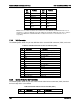
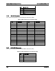
Figure 48. System Status LED (A), 5V StandBy LED (B), and ID LED (C)
Revision 1.9 157