
Technical Product Specification


Intel® Server Board S1600JP TPS Platform Management Functional Overview
system is reset or powered-on and POST completes, as indicated by the assertion of the POST-
complete signal. Additionally, the BMC should cancel any pending reads of the RTC if the
POST-complete signal deasserts (for example, due to a reset). Normally the BMC reads the
RTC when AC power is first applied and before the system is powered-on, so this is not a
concern. However, if AC power is applied and the power button is immediately pressed, it is
possible that POST would be in progress by the time the BMC is ready to read the RTC.
Another potential conflict can occur if the BMC gets reset and POST is in progress when the
BMC has re-initialized. For either of these cases, the BMC FW initializes its internal time clock
to 0 and begins counting up from there. When POST completes, BIOS will then update the
BMC’s time clock to the current system time.
The BMC’s internal timestamp clock is read and set using the Get SEL Time and Set SEL Time
commands, respectively. The Get SDR Time command can also be used to read the timestamp
clock. These commands and the IPMI time format are specified in the IPMI 2.0 specification.
Whenever the BMC receives the Set SEL Time command, it updates only its internal time clock.
Note that an update of this internal time clock does not result in a change to the system RTC.
4.5
Sensor Monitoring
The BMC monitors system hardware and reports system health. The information gathered from
physical sensors is translated into IPMI sensors as part of the “IPMI Sensor Model”. The BMC
also reports various system state changes by maintaining virtual sensors that are not
specifically tied to physical hardware.
4.6
Messaging Interfaces
The supported BMC communication interfaces include:
Host SMS interface by means of low pin count (LPC)/keyboard controller style
(KCS) interface
Host SMM interface by means of low pin count (LPC)/keyboard controller style
(KCS) interface
Intelligent Platform Management Bus (IPMB) I
2
C interface
LAN interface using the IPMI-over-LAN protocols
4.6.1
Channel Management
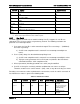
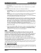
Every messaging interface is assigned an IPMI channel ID by IPMI 2.0. Commands are
provided to configure each channel for privilege levels and access modes. The following table
shows the standard channel assignments:
Table 14. Standard Channel Assignments
Channel ID
Interface
Supports Sessions
0
Primary IPMB
No
1
LAN 1
Yes
2
LAN 2
Yes
3
LAN3
1
(Provided by the Intel
®
Dedicated Server Management NIC)
Yes
40 Revision 1.9