
Technical Product Specification


Connector/Header Locations and Pin-out Intel® Server Board S1600JP TPS
Pin
Signal Name
4
GND
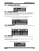
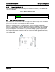
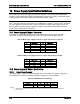
One Type A USB connector on the server board provide an option to support UBS device. The
pin-out is detailed in the following table.
Table 75. Type A USB connector Pin-Out (J1D2)
Pin
Signal Name
1
+5V
2
USB_N
3
USB_P
4
GND
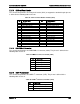
Two 2x5 connectors on the server board provide an option to support four additional internal
USB ports (J6E2 and J2D1). The pin-out is detailed in the following table and so on.
Table 76. Internal USB Connector Pin-Out (J6E2 and J2D1)
Pin
Signal Name
Pin
Signal Name
1
+5V
2
+5V
3
USB_N
4
USB_N
5
USB_P
6
USB_P
7
GND
8
GND
9
Key Pin
10
NC
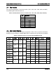
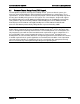
7.3.12
TPM Connector
The server board provides one TPM connector (J6B2) to support the TPM module. The pin-out
is defined in the following table and so on.
Table 77. TPM Connector Pin-Out (J6B2)
Pin
Signal Name
Pin
Signal Name
1
Key Pin
2
LPC_LAD<1>
3
LPC_LAD<0>
4
GND
5
IRQ_SERIAL
6
LPC_FRAME_N
7
P3V3
8
GND
9
RST_IBMC_NIC_N
10
CLK_33M_TPM
11
LPC_LAD<3>
12
GND
13
GND
14
LPC_LAD<2>
168 Revision 1.9