
Technical Product Specification

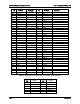


Intel® Server Board S1600JP TPS Connector/Header Locations and Pin-out
Pin
Signal Name
Pin
Signal Name
3
Green
4
G_RTN (Green Return)
5
Blue
6
B_RTN (Blue Return)
7
Vsync
8
GND
9
Hsync
10
KEY
11
DDC_SDA
12
VIDEO_IN_USE signal
13
DDC_SCL
14
+5V (fused, not populated)
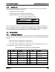
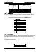
7.3.4
NIC Connectors
The server board provides four RJ-45 connectors on the back edge of the board (JA4A1 and
JA3A1). The pin-out for NIC connectors are identical and are defined in the
following table.
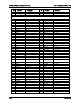
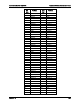
Table 67. RJ-45 10/100/1000 NIC Connector Pin-out (JA4A1 and JA3A1)
Pin
Signal Name
1
NIC_0_0_DP
2
NIC_0_0_DN
3
NIC_0_CT1
4
NIC_0_1_DP
5
NIC_0_1_DN
6
NIC_0_CT2
7
NIC_0_2_DP
8
NIC_0_2_DN
9
NIC_0_CT3
10
NIC_0_3_DP
11
NIC_0_3_DN
12
NIC_0_CT4
13
LED_NIC_LINK0_100_N
14
LED_NIC_LINK0_1000_R_N
15
LED_NIC_LINK0_LNKUP_N
16
LED_NIC_LINK0_ACT_R_N
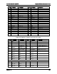
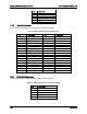
7.3.5
SATA Connectors
The server board provides six SATA port connectors which including two 6Gb/s SATA ports with
white connectors (J6E1 and J2E2) and four 3Gb/s SATA ports with black connectors (J2E1,
J2E3, J1E3, and J2D3).
SATA_0 (J6E1) can support SATA DOM. The SATA_1 (J2E2) cannot support SATA DOM from
the mechanical fitting with the board.
The pin configuration for each connector is identical and defined in the following table.
Table 68. SATA Connectors Pin-Out (J6E1, J2E2, J2E1, J2E3, J1E3, and J2D3)
Pin
Signal Name
1
GND
Revision 1.9 165