
Technical Product Specification


Intel® Server Board S1600JP TPS Connector/Header Locations and Pin-out
7.
Connector/Header Locations and Pin-out
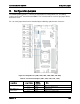
7.1
Power Connectors
To facilitate customers who want to cable to this board from a power supply, the power
connectors are implemented through one 10-pin connector and one 8-pin connector.
Table 55. Main Power Supply Connector 10-pin 2x5 Connector Pin-Out (J4K1)
Pin
Signal Name
Pin
Signal Name
1
PSON
6
5VSB
2
GND
7
PWROK
3
GND
8
3.3V
4
GND
9
3.3V
5
5V
10
Reserved
Table 56. Main Power Supply Connector 8-pin 2x4 Connector Pin-Out (J6K1)
Pin
Signal Name
Pin
Signal Name
1
GND
5
+12V
2
GND
6
+12V
3
GND
7
+12V
4
GND
8
+12V
7.2
System Management Headers
7.2.1
Intel
®
Remote Management Module 4 (Intel
®
RMM4 Lite) Connector
A 7-pin Intel
®
RMM4 Lite connector (J6A2) is included on the server board to support the
optional Intel
®
Remote Management Module 4. There is no support for third-party management
cards on this server board.
Note: This connector is not compatible with the Intel
®
Remote Management Module 3
(Intel
®
RMM3).
Table 57. Intel
®
RMM4 Lite Connector Pin-out (J6A2)
Pin
Signal Description
Pin
Signal Description
1
P3V3_AUX
2
SPI_BMC_BK_DI
3
Key Pin
4
SPI_BMC_BK_CLK
5
SPI_BMC_BK_DO
6
GND
7
SPI_BMC_BK_CS_N
8
GND
Revision 1.9 155