
Technical Product Specification


Intel® Server Board S1600JP TPS Configuration Jumpers
before any video or console is available. Once the system boots to this recovery image file
(FVMAIN.FV), it boots automatically into the EFI Shell to invoke the Startup.nsh script and start
the flash update application (IFlash32.efi). IFlash32.efi requires the supporting BIOS Capsule
image file (*Rec.CAP).
After the update is complete, a message displays, stating the BIOS has been updated
successfully. This indicates the recovery process is finished.
The user should then switch the recovery jumper back to normal operation and restart the
system by performing a power cycle.
The following steps demonstrate this recovery process:
1. Power OFF the system.
2. Insert recovery media.
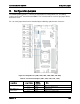
3. Switch the recovery jumper. Details regarding the jumper ID and location can be obtained
from the Board EPS for that Platform.
4. Power ON the system.
5. The BIOS POST screen will appear displaying the progress, and the system automatically
boots to the EFI SHELL.
6. The Startup.nsh file executes, and initiates the flash update (IFlash32.efi) with a new
capsule file (*Rec.CAP). The regular iFlash message displays at the end of the process—
once the flash update succeeds.
7. Power OFF the system, and revert the recovery jumper position to "normal operation".
8. Power ON the system.
9. Do NOT interrupt the BIOS POST during the first boot.
6.5
Reset BIOS Settings (J2B5)
The former name for this jumper is CMOS Clear. It is used to be the BIOS reset jumper. Since
the previous generation, the BIOS has moved CMOS data to the NVRAM region of the BIOS
flash. The BIOS checks during boot to determine if the data in the NVRAM needs to be set to
default. (Same function as F9 in BIOS that loads BIOS by default.)
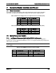
Table 59. Reset BIOS Jumper
Jumper Position
Mode of Operation
Note
1-2
Normal
Normal mode.
2-3
Clear BIOS settings
BIOS settings are reset to factory default.
Steps to clear BIOS settings:
1. Power down server. Do not unplug the power cord.
2. Open the server chassis. For instructions, see your Server Chassis Documentation.
3. Move jumper (J1D5) from the default operating position, covering pins 1 and 2, to the
reset/clear position, covering pins 2 and 3.
4. Wait five seconds.
Revision 1.9 153