
System Service Guide


Appendix C: LED Decoder
52 Intel
®
Server System R1000JP Family Service Guide
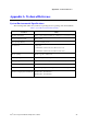
The LEDs are decoded as follows:
Table 9. POST Progress Code LED Example
LEDs
Upper Nibble LEDs Lower Nibble LEDs
MSB LSB
LED #7 LED #6 LED #5 LED #4 LED #3 LED #2 LED #1 LED #0
8h 4h 2h 1h 8h 4h 2h 1h
Status ON OFF ON OFF ON ON OFF OFF
Results
1 0 1 0 1 1 0 0
Ah Ch
• Upper nibble bits = 1010b = Ah;
• Lower nibble bits = 1100b = Ch;
The two are concatenated as Ach.
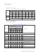
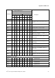
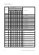
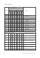
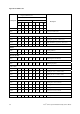
Table 10. Diagnostic LED POST Code Decoder
Checkpoint
Diagnostic LED Decoder
Description
1 = On, 0=Off
Upper Nibble Lower Nibble
MSB LSB
8h 4h 2h 1h 8h 4h 2h 1h
LED
#7 #6 #5 #4 #3 #2 #1 #0
Host Processor
0x10h 0 0 0 1 0 0 0 0
Power-on initialization of the host processor
(bootstrap processor)
0x11h 0 0 0 1 0 0 0 1 Host processor cache initialization (including AP)
0x12h 0 0 0 1 0 0 1 0 Starting application processor initialization
0x13h 0 0 0 1 0 0 1 1 SMM initialization
Chipset
0x21h 0 0 1 0 0 0 0 1 Initializing a chipset component
Memory
0x22h 0 0 1 0 0 0 1 0
Reading configuration data from memory (SPD on
FBDIMM)
0x23h 0 0 1 0 0 0 1 1 Detecting presence of memory