
Technical Product Specification


IntelP
®P
Server System R1000JP Family TPS System Storage and Peripheral Options
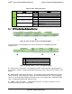
Table 36. Drive Activity LED States
Green
Condition
Drive Type
Behavior
Power on with no drive activity
SAS
LED stays on
SATA
LED stays off
Power on with drive activity
SAS
LED blinks off when processing a command
SATA
LED blinks on when processing a command
Power on and drive spun down
SAS
LED stays off
SATA
LED stays off
Power on and drive spinning up
SAS
LED blinks
SATA
LED stays off
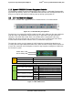
5.1.1 2.5” Drive Hot-Swap Backplane Overview
Figure 28. The Front side of 8 X 2.5” Hotswap Backplane
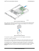
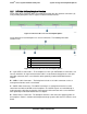
On the backside of each backplane are several connectors. The following illustration
identifies each.
Label
Description
A
Power connector
B
4-port Mini-SAS cable connectors
C
SMBus*-In cable connector – From Server board
Figure 29. The Back Side of 8 X 2.5” Hotswap Backplane
A – Power Harness Connector – The backplane includes a 2x2 connector supplying power to
the backplane. Power is routed to the backplane through a power cable harness from the server
board.
B – Multi-port Mini-SAS Cable Connectors – The backplane includes two multi-port mini-SAS
cable connectors, each providing I/O signals for four SAS/SATA hard drives on the backplane.
Cables can be routed from matching connectors on the server board, add-in SAS/SATA RAID
cards, or optionally installed SAS expander cards.
C – SMBus* Cable Connectors – The backplane includes a 1x5 cable connector used as a
management interface to the server board.
Revision 1.7 43
Intel
order number: G71652-008