
R2000GZ and R2000GL


Intel
®
Server System R2000GZ/GL Product Family TPS
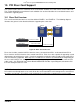
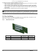
10. PCI Riser Card Support
The system includes two riser card slots on the server board. Available riser cards can be used in either slot.
This section will provide an overview of each available riser card and describe the server board features and
architecture supporting them.
10.1 Riser Slot Overview
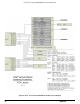
The server board includes two riser card slots labeled “RISER 1” and “RISER 2”. The following diagram
illustrates the general server board architecture supporting these two slots.
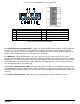
Figure 47. Riser Slot Architecture
Riser slot-1 includes a total of 24 PCIe Gen3 bus lanes; 16 routed from CPU-1 and 8 routed from CPU-2.
Riser slot-2 has 24 PCIe Gen3 bus lanes routed from CPU-2. Each riser slot is capable of supporting several
different types of multi-slot riser cards. In order to support the maximum number of add-in cards, both CPU-1
and CPU-2 must be populated. With only CPU-1 installed, riser slot-2 has no functionality and depending on
the riser card installed, riser slot-1 will be limited to supporting a single x16 PCIe add-in card or two x8 PCIe
add-in cards. See
Figure 48. Intel
®
Server Board S2600GZ/GL PCI Bus Layout Diagram, to determine PCI
bus lane routing for each riser card.
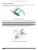
NOTE: The riser card slots on the server board are designed to support riser cards only. Inserting a
PCIe add-in card directly into the riser card slot on the server board will result in damage to the server board,
the add-in card, or both. PCIe add-in cards should only be installed into a supported riser card assembly.
CPU 1
CPU 2
x16 PCIe Gen3 32GB/s
x8 PCIe Gen3 16GB/s
x24 PCIe Gen3 48GB/s
Riser Slot 2
Riser Slot 1
X24 PCIe Gen3
X24 PCIe Gen3
Revision 2.2
65