Intel® Server System R1000BB Family Service Guide A Guide for Technically Qualified Assemblers of Intel® identified Subassemblies/Products Order Number: G65886-002
Disclaimer Disclaimer ® Information in this document is provided in connection with Intel products. No license, express or implied, by estoppel or otherwise, to any intellectual property rights is granted by this document.
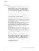
Safety Information Safety Information Important Safety Instructions Read all caution and safety statements in this document before performing any of the instructions. ® See also Intel Server Boards and Server Chassis Safety Information on the Intel® Server Deployment Toolkit 3.0 CD and/or at http://www.intel.com/support/motherboards/server/sb/cs-010770.htm. Wichtige Sicherheitshinweise Lesen Sie zunächst sämtliche Warnund Sicherheitshinweise in diesem Dokument, bevor® Sie eine der Anweisungen ausführen.
Warnings Warnings Heed safety instructions: Before working with your server product, whether you are using this guide or any other resource as a reference, pay close attention to the safety instructions. You must adhere to the assembly instructions in this guide to ensure and maintain compliance with existing product certifications and approvals. Use only the described, regulated components specified in this guide.
Preface Preface About this Manual This manual is written for system technicians who are responsible for troubleshooting, upgrading, and repairing this server system. This document provides a brief overview of the features of the server board/chassis, a list of accessories or other components you may need, troubleshooting information, and instructions on how to add and replace components on the Intel® Server System R1000BB family products. For the latest revision of this manual, go to http://www.intel.
Table of Contents Table of Contents Safety Information .................................................................................................iii Preface ....................................................................................................................v 1 Server System Features ......................................................................................1 Server System Feature Overview .....................................................................................
Table of Contents Installing a PCI Add-in Card ..........................................................................................29 Removing a PCI Add-in Card .........................................................................................30 Replacing a PCI Riser Card.....................................................................................................30 Removing a PCI Riser Card ...........................................................................................
Table of Contents Appendix B: Regulatory and Compliance Information ..........................................51 Appendix C: Getting Help .....................................................................................52 Warranty Information ....................................................................................................52 Appendix D: Intel® Server Issue Report Form .......................................................
List of Figures List of Figures Figure 1. Intel® Server System R1000BB ....................................................................................1 Figure 2. Intel® Server System R1000BB Components ...............................................................4 Figure 3. 3.5" Hard Drive Bay - 4 Drive Configuration .................................................................4 Figure 4. 2.5" Hard Drive Bay - 8 Drive Configuration ................................................................
List of Figures Figure 50. Installing the Plastic Guide to the Optical Drive ........................................................32 Figure 51. Installing an Optical Drive .........................................................................................32 Figure 52. Removing the Slimline Optical Drive ........................................................................33 Figure 53. Installing Intel® I/O Expansion Module ......................................................................
List of Tables List of Tables Table 1. Server System References............................................................................................ v Table 2. Intel® Server System R1000BB Feature Summary ........................................................1 Table 3. Hard Disk Drive Options ..............................................................................................10 Table 4. BIOS Setup: Keyboard Command Bar .....................................................................
Server System Features 1 Server System Features This chapter briefly describes the main features of the Intel® Server System R1000BB family. This includes illustrations of the products, a list of the server system features, and diagrams showing the location of important components and connections on the server systems. Figure 1. Intel® Server System R1000BB Server System Feature Overview Table below sumarizes the features of the the server systems. Table 2.
Server System Features Feature Description ® Processor Support Memory Chipset External I/O connections Internal I/O connectors / headers ® Support for one or two Intel Xeon processors E5-2400 product family with a Thermal Design Power (TDP) of up to 95 Watts.
Server System Features Server Management Power Supply Options The server system can have up to two power supply modules installed, providing support for the following power configurations: 1+0, 1+1 Redundant Power, and 2+0 Combined Power Three power supply options: o AC 460W Gold o AC 750W Platinum Storage Bay Options 4x – 3.5” SATA/SAS Hot Swap Hard Drive Bays + Optical Drive support 8x – 2.
Server System Features Server System Components This section helps you identify the components of your server system. If you are near the system, you can also use the Quick Reference Label provided on the inside of the chassis cover to assist in identifying components. Figure 2. Intel® Server System R1000BB Components Hot Swap Hard Drive Bay and Front Panel Options Figure 3. 3.5" Hard Drive Bay - 4 Drive Configuration Figure 4. 2.
Server System Features Front Panel Label A Description System ID Button w/Integrated LED Label F Description System Status LED B NMI Button (recessed, tool required for use) G Power Button w/Integrated LED C NIC-1 Activity LED H Hard Drive Activity LED D NIC-3 Activity LED I NIC-4 Activity LED E System Cold Reset Button J NIC-2 Activity LED Figure 5. Front Panel Options Back Panel Figure 6.
Server System Features Server Board Components This section helps you identify the components and connectors on the server board. Figure 7.
Server System Features Intel® Light-Guided Diagnostics A B C D E F G H System ID LED System Status LED POST Code Diagnostic LEDs System Power Good LED CPU-1 Fault LED 12V Standby LED DIMM Fault LEDs System Fan – 6 Fault LED I J K L M N O P System Fan – 5 Fault LED System Fan – 4 Fault LED System Fan – 3 Fault LED System Fan – 2 Fault LED System Fan – 1 Fault LED DIMM Fault LEDs CPU-2 Fault LED CATERR LED Figure 8.
Server System Features B - The System Status LED on the front and back panels shows the overall health of the system (green, blinking green, blinking amber, amber, off). C - POST Code Diagnostic LEDs on the server board change color or state (off, green, red, and amber) according to the POST sequence. D – System power good LED on the server board is illuminated when system power is good. P – CPU CATERR LED is illuminated when CPU CATERR error occurred.
Server System Features System Recovery Jumpers Jumper Name ® A Serial Jumper (J3A1) B BMC Force Update (J2D1) C BIOS Recover (J7D2) D Password Clear (J7E1) E ME Force Update (J7E2) F BIOS Default (J7E3) Intel Server System R1000BB Service Guide Jumper Purpose If pins 1-2 are selected, the serial-A configuration is in Data Carrier Detect (DCD) mode. These pins should be selected on 2-3 for normal system operation. If pins 2-3 are selected, the Integrated BMC Force Update Mode is enabled.
Server System Features Figure 9. Configuration Jumpers Peripheral Devices The Intel® Server System R1000BB provides locations and hardware for installing hard drives, CDROM drive, or DVD-ROM drive. The following figure shows the available options. A System Label Pull-out B Slimline Optical Drive Bay C Video Port D USB Ports E Front Control Panel F Hard Disk Drive Bays Figure 10. Optional Peripherals (8x2.
Server System Features Slimline Optical Drive Support The system has support for a single optical drive. The optical drive is NOT hot-swappable. The system power must be turned off to insert or remove the slimline optical drive. For instructions on installing an optical drive, see “Installing or Removing a Slimline Optical Drive”.
Server System Features A B C D Power Connector SGPIO Connector I2C Connector SATA Connectors Figure 13. 4 x 3.5-inch Hard Drive Backplane Components (Rear View) 8 x 2.5-inch Hard Drive Backplane A SAS/SATA Hot-swap Connectors Figure 14. 8 x 2.5-inch Hard Drive Backplane Components (Front View) A B C Power Connectors Mini-SAS Connectors I2C Connector Figure 15. 8 x 2.
Hardware Installations and Upgrades 2 Hardware Installations and Upgrades Before You Begin Before working with your server product, pay close attention to the “Safety Information” at the beginning of this manual. Note: Whenever you service the system, you must first power down the server and unplug all peripheral devices and the power cord.
Hardware Installations and Upgrades Cable Routing When you add or remove components from your server system, make sure your cables are routed correctly before reinstalling the server system cover. Use caution to make sure no cables or wires are pinched and that the airflow from the fans is not blocked. Use the figures below to determine the correct cable routing. Note: Red lines are for power connection, dot lines are for optional device connection.
Hardware Installations and Upgrades For system with 4 x 3.5” hard drive bay: Figure 16. Cable Routing – 4 x 3.
Hardware Installations and Upgrades For system with 8 x 2.5” hard drive bay: Note: To activate the port SCU1 (4-7) on the server board, a proper Intel® RAID C600 Upgrade Key must be installed. For instructions, see Intel® RAID C600 Upgrade Key Installation Guide. Note: An optical drive can be installed to replace the Front Panel I/O. Figure 17. Cable Routing – 8 x 2.
Hardware Installations and Upgrades Fan Connections Use the figures below to determine the proper fan connections. Figure 18. System Fan Order Figure 19. Connecting the Fan Power Cables to the Mother Board Removing and Installing the Front Bezel Removing the Front Bezel If your system includes a front bezel, follow these steps to remove the front bezel: 1. Unlock the bezel if it is locked. 2. Remove the left end of front bezel from rack handle (see letter “A”). 3.
Hardware Installations and Upgrades Figure 20. Removing the Front Bezel Installing the Front Bezel Note: Before installing the bezel, you must install the rack handles. 1. Lock the right end of the front bezel to the rack handle (see letter “A”). 2. Push in the left side of the bezel until it clicks into place (see letter “B”). 3. Lock the bezel if needed. Figure 21.
Hardware Installations and Upgrades top cover, power down the server and unplug all peripheral devices and the power cable(s). Note: A non-skid surface or a stop behind the server system may be needed to prevent the server system from slding on your work surface. 1. Observe the safety and ESD precautions at the beginning of this book. 2. Turn off all peripheral devices connected to the server. Turn off the server. 3. Disconnect the power cord. 4. Remove the four screws (see letter "A"). 5.
Hardware Installations and Upgrades Removing and Installing the Air Duct Always operate your server system with the air duct in place. The air duct is required for proper airflow within the server system. Removing the Air Duct Remove the air duct by lifting straight up. Figure 24. Removing the Air Duct Installing the Air Duct Align the two holes on the air duct with the alignment pins on the chassis and install the air duct into place. Figure 25.
Hardware Installations and Upgrades Removing and Installing Processor The heatsink has thermal interface material (TIM) on the underside of it. Use caution so that you do not damage the thermal interface material. Use gloves to avoid sharp edges. Removing Processor Heatsink(s) The heatsink is attached to the server board/processor socket with captive fasteners. Using a #2 Phillips* screwdriver, loosen the four screws located on the heatsink corners in a diagonal manner using the following procedure: 1.
Hardware Installations and Upgrades 1. Open the Socket Lever. Push the level handle down and away from the socket to release it (see letter “A”). Rotate the lever open all the way (see letter “B”). Figure 27. Installing Processor – Open the Socket Lever 2. Open the Load Plate. Press the locking lever slightly to raise the load plate (see letter “A”). Open the load plate all the way (see letter “B”). Figure 28. Installing Processor – Open the Load Plate 3. Install the Processor.
Hardware Installations and Upgrades Figure 30. Installing Processor – Remove the Cover 5. Close the load plate all the way as shown. Figure 31. Installing Processor – Close the Load Plate 6. With your finger, push down on the load plate lever as shown. Close the socket lever and ensure that the load plate tab engages under the socket lever when fully closed. (see letter “B”). Figure 32. Installing Processor – Latch the Locking Lever Installing Processor Heatsink(s) 1.
Hardware Installations and Upgrades 5. Repeat steps C and D by giving each screw two rotations each time until each screw is lightly tightened up to a maximum of 8 inch-lbs torque (see letter “E”). 6. Figure 33. Installing Processor Heatsink Removing the Processor 1. Remove the processor heatsink, see Figure 26. 2. Open the socket lever, see Figure 27. 3. Open the load plate, see Figure 28. 4. Remove the processor. Installing and Removing Memory Installing Memory 1. Locate the DIMM sockets.
Hardware Installations and Upgrades Figure 34. Installing Memory Removing Memory 1. Locate the DIMM sockets. Gently spread the retaining clips at each end of the socket. The DIMM lifts from the socket. 2. Holding the DIMM by the edges, lift it from the socket, and store it in an anti-static package. Installing and Removing Hot-swap Hard Drive Caution: If you don't install all drives, empty drive bays must be occupied by carriers with plastic drive blank provided to maintain proper system cooling.
Hardware Installations and Upgrades Figure 36. Installing Hard Disk Drive – Removing 3.5” HDD interface bracket 3. Install the hard disk drive using the same four screws as shown. Make sure the connector end of the drive matches the backplane connector (see letter “D”). Figure 37. Installing Hard Disk Drive – Installing 3.5” HDD For installing 2.5” Hard Disk Drive as option: Break off the tab on the HDD interface bracket (see letter “d1”).Install the HDD interface bracket from top.
Hardware Installations and Upgrades Figure 39. Installing Hard Disk Drive – Inserting 3.5” HDD assembly Installing a Hard Disk Drive into 2.5” Hard Drive Carrier 1. Remove the drive carrier by pressing the green latch to unlock (see letter “A”). Pull out the black lever and slide the carrier out (see letter “B”). Figure 40. Installing Hard Disk Drive – Removing 2.5” HDD carrier 2. Remove the four screws securing the plastic drive blank from the 2.5" HDD carrier (see letter “C”).
Hardware Installations and Upgrades Figure 42. Installing Hard Disk Drive – Installing 2.5” HDD 4. With the lever open, insert the hard disk drive assembly into the chassis, then push in the lever to lock it into place (see letter “F”). Figure 43. Installing Hard Disk Drive – Inserting 2.5” HDD assembly Removing and Installing the PCI Riser Assembly Removing the PCI Riser Assembly Disconnect any cables attached to any add-in cards.
Hardware Installations and Upgrades — If you need to add or replace a PCI add-in card, see “Installing and Removing a PCI Add-in Card”. — If you need to add or replace a PCI riser card, see “Replacing a PCI Riser Card”. — If you removed the PCI riser assembly for another procedure, continue with that procedure. Installing the PCI Riser Assembly 1.
Hardware Installations and Upgrades Figure 46. Installing a PCI Add-In Card Removing a PCI Add-in Card 1. Remove the PCI riser assembly. For instructions, see “Removing the PCI Riser Assembly”. 2. Remove the screw as shown (see letter “A”). 3. Remove the PCI add-in cad from the riser card connector (see letter “B”). Figure 47. Removing a PCI Add-In Card Note: Make sure that all empty add-in card slots have filler panels installed.
Hardware Installations and Upgrades turn off the system by pressing the power button, and unplug the power cord from the system or wall outlet. Note: To eliminate the possibility of installing the replacement connector on the wrong side of the PCI riser assembly, replace one connector at a time. Removing a PCI Riser Card 1. Disconnect any cables attached to any add-in cards. 2. Remove the PCI riser assembly. For instructions, see “Removing the PCI Riser Assembly”. 3.
Hardware Installations and Upgrades To maintain proper system cooling, a filler panel must be installed if you do not install a device at this location. Installing a Slimline Optical Drive 1. Install the plastic guide onto the back of the drive and attach with two screws as shown (see letter “A”). Figure 50. Installing the Plastic Guide to the Optical Drive 2. Insert the optical drive into chassis opening and push all the way until it stops (see letter “B”). 3.
Hardware Installations and Upgrades Figure 52. Removing the Slimline Optical Drive 4. If no device will be installed in this location, install a filler panel in this location. Installing and Removing Intel® I/O Expansion Module ® Installing Intel I/O Expansion Module 1. Squeeze the sides of the filler panel to disengage it from the server system back panel and remove it (see letter “A”). 2. Position the module over the server board, fit the front of the module into the back panel slot (see letter “B”).
Hardware Installations and Upgrades ® Removing Intel I/O Expansion Module 1. Remove the three screws as shown (see letter “A”). 2. Remove the module out of the server system (see letter “B”). 3. Figure 54. Removing an I/O Expansion Module 4. Install the I/O expansion module filler panel into the system back panel. Installing and Removing the Intel® RAID C600 Upgrade Key Installing the Intel® RAID C600 Upgrade Key Locate the white 4-pin key header next to the SCU_0 and SCU-1 miniSAS connectors.
Hardware Installations and Upgrades Removing the Intel® RAID C600 Upgrade Key Pull up the key to remove it from the mother board. Installing and Removing the Intel® Remote Management Module 4 Installing the Intel® RMM4 Lite Locate the RMM4 Lite connector next to the POST diagnostic LEDs, carefully pickup the Intel® RMM4 Lite module, match the alignment pin of the module and the connector on server board, then press to install. Figure 56. Installing the Intel® RMM4 Lite Install the Intel® RMM4 NIC 1.
Hardware Installations and Upgrades Removing the Intel® RMM4 Lite Pull up the RMM4 Lite module to remove it from the mother board. Removing the Intel® RMM4 NIC 1. Remove the two screws as shown (see letter “A”). 2. Remove the module out of the server system (see letter “B”). 3. Figure 58. Removing the Intel® RMM4 NIC Installing and Removing the Intel® RAID Smart Battery Installing the Intel® RAID Smart Battery 1. Connect the cable between the BBU and the RAID card.
Hardware Installations and Upgrades 4. Figure 59. Installing the Intel® RAID Smart Battery Removing the Intel® RAID Smart Battery 1. Slide the plastic battery holder toward the front of the system to disengage it from the BBU bracket (see letter “A”). 2. Lift the battery up to remove it from the server chassis (see letter “B”). 3. Figure 60.
Hardware Installations and Upgrades - If a filler panel is installed, use the 'finger hole' to remove the filler panel (see letter “A”). Figure 61. Removing the filler panel - If a power supply is installed, push the green latch in the direction shown while pulling out of the system by the handle. Figure 62. Removing the power supply module 2. Do one of the following: - Insert the power supply module into the power supply cage and push all the way until it clicks into place (see letter “B”).
Hardware Installations and Upgrades Figure 64. Installing the filler panel Installing and Removing the Server Board Removing the Server Board 1. Lift the air duct straight up to remove from the server board 2. Disconnect all cables from the server board. Figure 65. Removing the Air Duct 3. Remove the nine screws from the server board. (see letter “A”). 4. Lift the server board from the server system. (see letter “B”).
Hardware Installations and Upgrades Figure 66. Removing the Server Board Installing the Server Board 1. Place the server board into the server system (see letter “A”). 2. Secure the server board with nine screws (see letter “B”).
Hardware Installations and Upgrades 3. Figure 67. Installing the Server Board 4. Install air duct onto the server board. Figure 68. Installing the Air Duct 5. Connect all power cables to the server board. Replacing the Backup Battery The lithium battery on the server board powers the RTC for up to 10 years in the absence of power.
Hardware Installations and Upgrades the RTC (for example, the date and time) may be wrong. Contact your customer service representative or dealer for a list of approved devices. Warning: Danger of explosion if battery is incorrectly replaced. Replace only with the same or equivalent type recommended by the equipment manufacturer. Discard used batteries according to manufacturer's instructions. Advarsel: Lithiumbatteri - Eksplosionsfare ved fejlagtig håndtering.
Hardware Installations and Upgrades Note: You will need to run the BIOS Setup to restore the configuration settings to the RTC. Replacing a System Fan Note: The system fans cannot be hot swapped. System power must be removed when replacing a system fan. 1. Disconnect the fan cable (see letter “A”). 2. Pull system fan straight up to remove it from the fan holder. Figure 70. Replacing a system fan 3. Replace the system fan. Replacing the Backplane Removing the Backplane 1.
Hardware Installations and Upgrades Figure 71. Removing the backplane Installing the Backplane 1. Remove all hot-swap drive carriers, regardless of whether or not a drive is installed in the carrier. 2. Hold the backplane only by the edges. Do not push or pull on any components on the backplane. Position the backplane in place at the front of the server system (see letter “A”). 3. Slide the backplane into the server system guides (see letter “B”). 4.
Hardware Installations and Upgrades Installing and Removing the Rack Handles Installing the Rack Handles Align the rack handle with the two holes on the side of the server system and attach the rack handle to the server system with two screws as shown. Figure 73. Installing the Rack Handle Removing the Rack Handles Remove the two screws holding the rack handle in place, and remove the rack handle from the server system as shown. Figure 74.
Server Utilities 3 Server Utilities Using the BIOS Setup Utility This section describes the BIOS Setup utility options, which is used to change server configuration defaults. You can run the BIOS Setup with or without an operating system being present. For information about specific BIOS setup screens, see the Intel® Server Board S2400BB Technical Product Specification. For a web link to this document, see “Additional Information and Software”.
Server Utilities Table 4. BIOS Setup: Keyboard Command Bar Key Option Description Execute Command The key is used to activate submenus when the selected feature is a submenu, or to display a pick list if a selected option has a value field, or to select a subfield for multivalued features like time and date. If a pick list is displayed, the key selects the currently highlighted item, undoes the pick list, and returns the focus to the parent menu.
Server Utilities Upgrading the BIOS Follow the instructions in the readme file that came with the BIOS upgrade. When the update completes, remove the bootable media from which you performed the upgrade. Caution: Do not power down the system during the BIOS update process! The system will reset automatically when the BIOS update process is completed. Note: You may encounter a CMOS Checksum error or other problem after reboot. If this happens, shut down the system and boot it again.
Appendix A: Technical Reference Appendix A: Technical Reference Power Supply Input Voltages 460W power supply module • 100 - 127 V at 50/60 Hz 5.8 A • 200 - 240 V at 50/60 Hz 2.9 A 750W power supply module • 100 - 127 V at 50/60 Hz 8.2 A • 200 - 240 V at 50/60 Hz 4.4 A Power Supply Output Voltages The following table lists the total wattage available from the power subsystem for each voltage. For information about calculating the power usage for your configuration, please use the Power Budget Tool.
Appendix A: Technical Reference Shipping 50% to 90%, non-condensing with a maximum wet bulb of 28° C (at temperatures from 25° C to 35° C) Operating Half sine, 2g, 11 mSec Unpackaged Trapezoidal, 25 g, velocity change is based on packaged weight Packaged Product Weight: ≥ 40 to < 80 Shock Non-palletized Free Fall Height = 18 inches Palletized (single product) Free Fall Height = NA Vibration Unpackaged 5 Hz to 500 Hz 2.20 g RMS random Packaged 5 Hz to 500 Hz 1.
Appendix B: Regulatory and Compliance Information Appendix B: Regulatory and Compliance Information Please refer to the Server Products Regulatory and Safety document for the product regulatory compliance reference. The document can be downloaded from http://www.intel.com/support/server.
Appendix C: Getting Help Appendix C: Getting Help If you encounter an issue with your server system, follow these steps to obtain support: 1. Visit the following Intel support web page: http://www.intel.com/support/ This web page provides 24x7 support when you need it to get the latest and most complete technical support information on all Intel Enterprise Server and Storage Platforms.
® Appendix D: Intel Server Issue Report Form Appendix D: Intel® Server Issue Report Form Issue Report Form (Rev 3.6) Note: Filling out this form completely is required for any escalation. Customer Contact Information: Customer Support Case#: Intel® Server Board or System: (Example: S2400BB, R1000BB) Server Chassis: (Example P4000M. If third-party chassis used, indicate make and model.
® Appendix D: Intel Server Issue Report Form Type Speed sSpec Thermal Solution Processor 1 Processor 2 Thermal solution (Heat sink) examples: (1U, Passive w/air ducting, Active w/fan, and so on) Memory: Manufacturer Part Number DRAM Part Number On Intel tested list? Add-in adapters (Example: NICs, Management Adapters, Serial Expansion Cards, PCI-Express* Adapters, RAID Controllers, SCSI Controllers, and so on): Type Slot Manufacturer Model Firmware Other third part hardware (Example: Exampl
® Appendix D: Intel Server Issue Report Form Storage Devices (Example: SCSI, SATA, SAS, USB, Tape, and so on): Manufacturer Model Type Size Firmware In Hot Swap Bay? Operating System Information (Example: RedHat* Enterprise Linux, Microsoft* Windows* Server 2003, Service pack 1, OEM CD): Manufacturer: Version: Language version (English, Arabic, Chinese (Simplified)): Service Pack Level or Kernel Revision: Distribution (OEM/Retail): Intel® RAID Controller: (Example SRCU42E) RAID controller part nu
® Appendix D: Intel Server Issue Report Form Troubleshooting tried: Steps to replicate the issue: 56 Intel ®® Server System R1000BB Service Guide
® Appendix D: Intel Server Issue Report Form Issue impact statements: Do you have any potential Intel system, or component purchases that this issue is holding up? If yes, please provide a brief description below. Do you have systems already purchased that are not being delivered to your customers because of this issue? If yes, please provide a brief description below.