
Intel Server System R2000BB Family
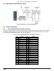


Intel
®
Server System R2000BB Product Family TPS
Revision
2.0
17
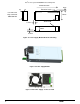
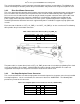
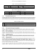
3.3.4 Optical Drive and SSD Power Connector
The server board includes one brown 2x3-pin power connector intended to provide power to an optionally
installed optical drive and up to two Solid State Devices (SSDs). On the server board this connector is labeled
as “ODD/SSD PWR”. The following table provides the pin-out for this connector.
Table 6. Peripheral Drive Power Connector Pin-out (“ODD/SSD PWR”)
Signal Description
Pin#
Pin#
Signal Description
P12V
4
1
P5V
P3V3
5
2
P5V
GROUND
6
3
GROUND
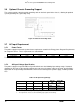
3.4 Power Supply Module Efficiency
The following tables provide the required minimum efficiency level at various loading conditions.
These are
provided at three different load levels: 100%, 50% and 20%.
Efficiency is tested over an AC input voltage
range of 115 VAC to 220 VAC.
Table 7. 460 Watt Power Supply Efficiency (Gold)
Loading
100% of maximum
50% of maximum
20% of maximum
10% of maximum
Minimum Efficiency
88%
92%
88%
80%
Table 8. 750 Watt Power Supply Efficiency (Platinum)
Loading
100% of maximum
50% of maximum
20% of maximum
10% of maximum
Minimum Efficiency
91%
94%
90%
82%
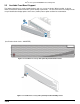
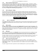
3.5 Power Cord Specification Requirements
Power cords used must meet the specification requirements listed in the following table.
Table 9. AC Power Cord Specifications
Cable Type
SJT
Wire Size
16 AWG
Temperature Rating
105ºC
Amperage Rating
13 A
Voltage Rating
125 V
Figure 19. AC Power Cord