
Intel Server System R1000BB Family


Intel
®
Server System R1000BB Product Family TPS
Revision 2.0 35
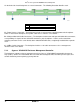
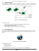
A – 7-pin SATA I/O Connectors – The backplane has four 7-pin SATA/SAS I/O connectors, one for each hard
drive. A single multi-connector cable is routed from the backplane to a four port mini-SAS connector on the
server board or other optionally installed SATA/SAS host bus adapter.
B –. SMBus Cable Connectors – The backplane includes a 1x5 cable connector used as a management
interface to the server board
C-. SGPIO Cable Connector – The SGPIO connector is a management interface used to control the hard drive
fault LEDs on the backplane. The SGPIO signals are routed through a multi-connectors cable that is routed to
a four port mini-SAS connector on the server board or other optionally installed SATA/SAS host bus adapter.
D - Power Harness Connector - The backplane includes a 2x2 connector supplying power to the backplane.
Power is routed to the backplane via a power cable harness from the server board
5.2.2 Cypress* CY8C22545 Enclosure Management Controller
The backplanes support enclosure management using a Cypress* CY8C22545 Programmable System-on-
Chip (PSoC*) device.
The CY8C22545 drives the hard drive activity/fault LED, hard drive present signal, and
controls hard drive power-up during system power-on.
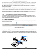
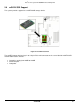
5.3 Optical Drive Support
Systems configured with four 3.5” hard drive bays also include a designated drive bay ‘A’ to support a SATA
optical drive as illustrated below.
Figure 25. Optical Drive Support
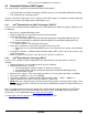
For systems that support eight 2.5” hard drives, the front I/O Panel, which provides video and USB ports, can
be replaced with a SATA optical drive.
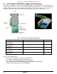
A 2x3 pin power connector on the server board labeled “ODD/SSD PWR”, is designed to provide power to the
optical drive. SATA signals for the optical drive are cabled from the white 7-pin single port SATA connector on
the server board.