
Intel Server System R1000BB Family


Intel
®
Server System R1000BB Product Family TPS
16 Revision 2.0
The server board provides several connectors to provide power to various system options. The following sub-
sections will identify the location; provide the pin-out definition; and provide a brief usage description for each.
3.3.2 Riser Card Power Connectors
The server board includes two white 2x2-pin power connectors that provide supplemental power to high power
PCIe x16 add-in cards (GPU) that have power requirements that exceed the 75W maximum power supplied by
the PCIe x16 riser slot. A cable from this connector may be routed to a power connector on the given add-in
card. Maximum power draw for each connector is 225W, but is also limited by available power provided by the
power supply and the total power draw of the rest of the system. A power budget for the complete system
should be performed to determine how much supplemental power is available to support any high power add-
in cards.
Note: Intel
®
Xeon Phi™ Coprocessor and non-Intel GPGPU add-in cards cannot be supported in a 1U server
system.
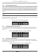
Each connector is labeled as “OPT_12V_PWR_1” and “OPT_12V_PWR_2” on the server board. The following
table provides the pin-out for both connectors.
Table 4. Riser Slot Power Pin-out ("OPT_12V_PWR_#")
Signal Description
Pin#
Pin#
Signal Description
P12V
3
1
GROUND
P12V
4
2
GROUND
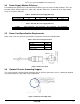
3.3.3 Hot Swap Backplane Power Connector
The server board includes one white 2x4-pin power connector that is cabled to the hot swap backplane. On
the server board, this connector is labeled as “HSBP PWR”. The following table provides the pin-out for this
connector.
Table 5. Hot Swap Backplane Power Connector Pin-out (“HSBP PWR")
Signal Description
Pin#
Pin#
Signal Description
P12V_240VA
5
1
GROUND
P12V_240VA
6
2
GROUND
P12V_240VA
7
3
GROUND
P12V_240VA
8
4
GROUND
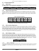
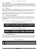
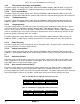
3.3.4 Optical Drive Power Connector
The server board includes one brown 2x3-pin power connector intended to provide power to an optionally
installed optical drive. On the server board this connector is labeled as “ODD/SSD PWR”. The following table
provides the pin-out for this connector.
Table 6. Peripheral Drive Power Connector Pin-out ("ODD/SSD PWR")
Signal Description
Pin#
Pin#
Signal Description
P12V
4
1
P5V
P3V3
5
2
P5V
GROUND
6
3
GROUND