
Intel Server Board S2400BB

Intel® Server Board S2400BB TPS
Revision 2.0
75
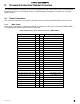
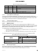
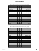
Amber
Solid on
Critical, non-
recoverable –
System is halted
Fatal alarm – system has failed or shutdown:
CPU CATERR signal asserted
MSID mismatch detected (CATERR also asserts for this case).
CPU 1 is missing
CPU Thermal Trip
No power good – power fault
DIMM failure when there is only 1 DIMM present and hence no good
memory present
1
.
Runtime memory uncorrectable error in non redundant mode.
DIMM Thermal Trip or equivalent
SSB Thermal Trip or equivalent
CPU ERR2 signal asserted
BMC\Video memory test failed. (Chassis ID shows blue/solid-on for this
condition)
Both uBoot BMC FW images are bad. (Chassis ID shows blue/solid-on for
this condition)
240VA fault
Fatal Error in processor initialization:
Processor family not identical
Processor model not identical
Processor core/thread counts not identical
Processor cache size not identical
Unable to synchronize processor frequency
Unable to synchronize QPI link frequency
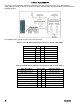
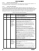
8.2.2 Front Panel USB Connector
The server board includes a 10-pin connector, that when cabled, can provide up to two USB ports to a front
panel. On the server board the connector is labeled “FP USB” and is located on the front edge of the board.
The following table provides the connector pin-out.
Table 30. Front Panel USB Connector Pin-out ("FP USB")
Signal Description
Pin#
Pin#
Signal Description
P5V_USB_FP
1
2
P5V_USB_FP
USB2_P11_F_DN
3
4
USB2_P13_F_DN
USB2_P11_F_DP
5
6
USB2_P13_F_DP
GROUND
7
8
GROUND
10
TP_USB2_FP_10
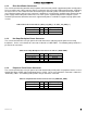
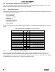
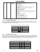
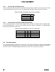
8.2.3 Front Panel Video Connector
The server board includes a 14-pin header, that when cabled, can provide an alternate video connector to the
front panel. On the server board this connector is labeled “FP VIDEO” and is located on the front edge of the
board. When a monitor is attached to the front panel video connector, the external video connector located on
the back edge of the board is disabled. The following table provides the pin-out for this connector.
Table 31. Front Panel Video Connector Pin-out ("FP VIDEO")
Signal Description
Pin#
Pin#
Signal Description
V_IO_FRONT_R_CONN
1
2
GROUND
V_IO_FRONT_G_CONN
3
4
GROUND
V_IO_FRONT_B_CONN
5
6
GROUND
V_BMC_GFX_FRONT_VSYN
7
8
GROUND
V_BMC_GFX_FRONT_HSYN
9
KEY
V_BMC_FRONT_DDC_SDA_CONN
11
12
V_FRONT_PRES_N
V_BMC_FRONT_DDC_SCL_CONN
13
14
P5V_VID_CONN_FNT