
Intel Server Board S2400BB

Intel® Server Board S2400BB TPS
Revision 2.0
72
8.2 Front Panel Headers and Connectors
The server board includes several connectors that provide various possible front panel options. This section
provides a functional description and pin-out for each connector.
8.2.1 Front Panel Support
Included on the front edge of the server board is a 30-pin SSI compatible front panel header which provides for
various front panel features including:
• Power/Sleep Button
• System ID Button
• System Reset Button
• NMI Button
• NIC Activity LEDs
• Hard Drive Activity LEDs
• System Status LED
• System ID LED
On the server board, this header is labeled “FRONT PANEL”. The following table provides the pin-out for this
header.
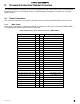
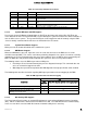
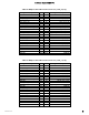
Table 26. SSI Front Panel Header Pin-out ("Front Panel")
Signal Description
Pin#
Pin#
Signal Description
P3V3_AUX
1
2
P3V3_AUX
KEY
4
P5V_STBY
FP_PWR_LED_BUF_R_N
5
6
FP_ID_LED_BUF_R_N
P3V3
7
8
FP_LED_STATUS_GREEN_R_N
LED_HDD_ACTIVITY_R_N
9
10
FP_LED_STATUS_AMBER_R_N
FP_PWR_BTN_N
11
12
LED _NIC_LINK0_ACT_FP_N
GROUND
13
14
LED _NIC_LINK0_LNKUP_FP_N
FP_RST_BTN_R_N
15
16
SMB_SENSOR_3V3STBY_DATA_R0
GROUND
17
18
SMB_SENSOR_3V3STBY_CLK
FP_ID_BTN_R_N
19
20
FP_CHASSIS_INTRUSION
PU_FM_SIO_TEMP_SENSOR
21
22
LED_NIC_LINK1_ACT_FP_N
FP_NMI_BTN_R_N
23
24
LED_NIC_LINK1_LNKUP_FP_N
KEY
KEY
LED_NIC_LINK2_ACT_FP_N
27
28
LED_NIC_LINK3_ACT_FP_N
LED_NIC_LINK2_LNKUP_FP_N
29
30
LED_NIC_LINK3_LNKUP_FP_N
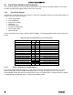
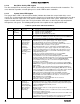
8.2.1.1 Power / Sleep Button and LED Support
Pressing the Power button will toggle the system power on and off. This button also functions as a sleep
button if enabled by an ACPI compliant operating system. Pressing this button will send a signal to the
integrated BMC, which will power on or power off the system. The power LED is a single color and is capable
of supporting different indicator states as defined in the following table.