
Intel Server System R1000BB Family


Intel
®
Server System R1000BB Product Family TPS
Revision 2.0 49
Note: Some half-height PCIe add-in cards installed in Riser Card #1, were found to interfere with the Intel
®
Integrated RAID Module when installed on the backside of the Butterfly riser card option for Riser #2. Properly
installed add-in cards should have no contact between them. Intel does NOT recommend operating a server
system when contact is observed between add-in cards.
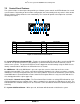
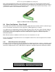
Figure 37. 1U Riser Card #1 Assembly Drawing
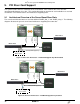
9.4 Riser Card Options – Riser Slot #2
The number of PCIe bus lanes routed to Riser Slot #2 is dependent on the number of CPUs installed, the type
of riser card installed, and whether or not an 8-port Intel
®
C600 Upgrade Key is installed.
In a single processor configuration, by default CPU #1 will route x8 PCIe bus lanes to Riser Slot #2. However,
should the system be configured with an 8-port Intel
®
C600 Upgrade Key, four of eight PCIe bus lanes from
CPU #1 will be routed via a multiplexor to the Intel
®
C602 chipset to support the embedded 8-port SCU
SATA/SAS controller.
With CPU #2 installed, an additional x16 PCIe bus lanes are routed to the riser slot.
PCI bus lane utilization is dependent on the riser card option installed. Riser cards designed for Riser Slot #2
include the following
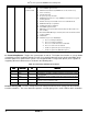
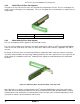
9.4.1 1-Slot PCIe x8 Riser Card (default)
Using this riser card, x8 PCIe bus lanes are routed to Riser Slot #2 from CPU #1. However, should the system
be configured with a an 8-port Intel
®
C600 Upgrade Key, four of the eight PCIe bus lanes from CPU #1 will be
routed via a multiplexor to the Intel
®
C602 chipset to support the embedded 8-port SCU SATA/SAS controller.
Slot Description
PCI Lane Routing Riser Slot #2
PCIe x8 lanes, x16 slot
CPU1 with no RAID Key installed
PCIe x4 lanes, x16 slot
CPU1 with 8-port RAID Key installed