
Intel Server System R1000BB Family


Intel
®
Server System R1000BB Product Family TPS
48 Revision 2.0
9.2 Riser Card Support
NOTE: The riser card slots on the server board are designed to support riser cards only. Inserting a PCIe add-
in card directly into the riser card slot on the server board will result in damage to the server board, the add-in
card, or both. PCIe add-in cards should only be installed into a supported riser card assembly.
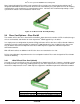
The system has concurrent support for two riser cards. Each riser card is mounted to a bracket assembly and
is installed into the system by aligning the edge connector of the riser card with the matching slot connector on
the server board, and with hooks on the bracket assembly to slots on the back edge of the chassis.
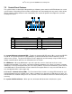
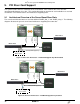
Figure 36. Add-in Card Support
The system has several riser card options. Riser cards for this server are NOT interchangeable between riser
slots.
Caution: Riser cards are NOT interchangeable between Riser Slot #1 and Riser Slot #2. The riser card
assembly for Riser #1 will include a mechanical block to prevent accidental insertion into Riser Slot #2.
Do not install a Riser Slot #1 riser card into Riser Slot #2. Doing so will electrically damage the riser
card, riser slot, or both.
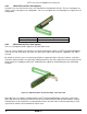
9.3 Riser Card Options – Riser Slot #1
All x16 PCIe bus lanes for Riser Slot #1 on the server board are routed from CPU #1. The default riser card
designed for Riser Slot #1 includes a single PCIe x16 (x16 lanes, x16 slot) add-in slot that can support a single
full-height, half-length PCIe add-in card. However, add-in card size maybe limited to half-height, half-length
PCIe add-in cards when the following options are configured:
• A cable is installed into either mini-SAS SCU connector
• An Intel
®
Integrated RAID Module is installed into the rear facing add-in PCIe slot from the butterfly riser
card option installed in Riser Slot #2.