
Intel Server System R1000BB Family


Intel
®
Server System R1000BB Product Family TPS
Revision 2.0 41
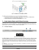
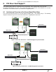
Figure 29. AXXBBU09 and AXXRFMBU2 Installation
For additional product information, please reference the following Intel document:
• Intel Integrated RAID Module RMS25PB080, RMS25PB040, RMS25CB080, and RMS25CB040
Hardware Users Guide – Intel Order Number G37519-001
• Intel
®
Raid Maintenance Free Backup Unit AXXRMFBU2 User’s Guide
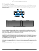
7. Front Control Panel and I/O Panel Overview
On the front panel of all system configurations is a Control Panel providing push button system controls and
LED indicators for several system features, and an I/O Panel providing USB ports and a video connector. This
section describes the features and functions of both front panel options.
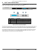
7.1 I/O Panel Features
Label
Description
A
Video connector
B
USB ports
Figure 30. Front I/O Panel Features
A – Video connector – The front I/O Panel video connector gives the option of attaching a monitor to the front
of the system. When BIOS detects that a monitor is attached to the front video connector, it disables the video
signals routed to the on-board video connector on the back of the system. Video resolutions from the front
video connector may be lower than that of the rear on-board video connector. A short video cable should be
used for best resolution. The front video connector is cabled to a 2x7 header on the server board labeled “FP
Video”.
B – USB Ports – The front I/O panel includes two USB ports. The USB ports are cabled to a 2x5 connector on
the server board labeled “FP USB”.
Note – On systems that support 8x2.5” hard drives, the I/O Panel can be replaced with a SATA optical drive.