
Intel Server System R1000BB Family

Intel
®
Server System R1000BB Product Family TPS
Revision 2.0 27
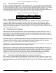
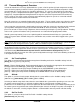
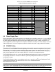
The following diagram illustrates the fan speed control structure
Figure 20. Fan Control Model
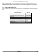
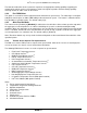
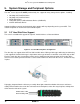
4.3 System Fans
Five managed dual rotor 40mm x 56mm system fans and an embedded fan for each installed power supply,
provide the primary airflow for the system. The system is designed for fan redundancy when configured with
two power supply modules. Should a single fan fail (system fan or power supply fan), platform management
will adjust air flow of the remaining fans and manage other platform features to maintain system thermals. Fan
redundancy is lost if more than one fan is in a failed state
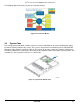
Figure 21. System Fan Identification