
Intel Server Board S2400BB


Intel® Server Board S2400BB TPS
Revision 2.0
71
8.1.2 Riser Card Power Connectors
The server board includes two white 2x2-pin power connectors that provide supplemental power to high power
PCIe x16 add-in cards (GPU) that have power requirements that exceed the 75W maximum power supplied by
the PCIe x16 riser slot. A cable from this connector may be routed to a power connector on the given add-in
card. Maximum power draw for each connector is 225W, but is also limited by available power provided by the
power supply and the total power draw of the rest of the system. A power budget for the complete system
should be performed to determine how much supplemental power is available to support any high power add-
in cards.
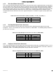
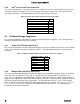
Table 23. Riser Slot Power Pin-out ("OPT_12V_PWR_1" & " OPT_12V_PWR_2")
Signal Description
Pin#
Pin#
Signal Description
P12V
3
1
GROUND
P12V
4
2
GROUND
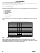
8.1.3 Hot Swap Backplane Power Connector
The server board includes one 8-pin power connector that can be cabled to provide power for hot swap
backplanes. On the server board, this connector is labeled as “HSBP PWR”. The following table provides the
pin-out for this connector.
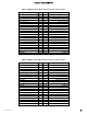
Table 24. Hot Swap Backplane Power Connector Pin-out (“HSBP PWR")
Signal Description
Pin#
Pin#
Signal Description
P12V_240VA1
5
1
GROUND
P12V_240VA1
6
2
GROUND
P12V_240VA2
7
3
GROUND
P12V_240VA2
8
4
GROUND
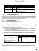
8.1.4 Peripheral Drive Power Connector
The server board includes one 6-pin power connector intended to provide power for peripheral devices such as
Optical Disk Drives (ODD) and/or Solid State Devices (SSD). On the server board this connector is labeled as
“ODD/SSD_ PWR”. The following table provides the pin-out for this connector.
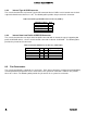
Table 25. Peripheral Drive Power Connector Pin-out ("ODD/SSD_PWR")
Signal Description
Pin#
Pin#
Signal Description
P12V
4
1
P5V
P3V3
5
2
P5V
GROUND
6
3
GROUND