
Intel Server Board S2400BB


Intel® Server Board S2400BB TPS
Revision 2.0
70
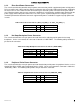
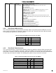
For server systems requiring support for redundant power, two connectors on the server board labeled
“PDB_PWR” and “PDB_CTRL can be used to connect a separate power distribution board as illustrated in the
following diagram.
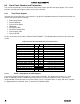
The following tables provide the pin-out for each connector.
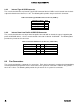
Table 21. Power Distribution Board Power Connector Pinout (“PDB_PWR”)
Signal Description
Pin #
Pin#
Signal Description
P12V
8
1
GROUND
P12V
9
2
GROUND
P12V
10
3
GROUND
P12V
11
4
GROUND
P12V
12
5
GROUND
P12V
13
6
GROUND
P12V
14
7
GROUND
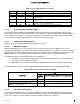
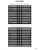
Table 22. Power Distribution Board Control Connector Pinout ("PDB_CTRL")
Signal Description
Pin #
Pin#
Signal Description
SMB_PMBUS_DATA_R
1
2
PD_PS2_FRU_A0
SMB_PMBUS_CLK_R
3
4
PD_PS2_FRU_A1
FM_PS_EN_PSU_N
5
6
P12V_SHARE
IRQ_SML1_PMBUS_ALERT_R3_N
7
8
FM_PS_CR1
ISENSE_P12V_SENSE_RTN
9
10
PWRGD_PS_PWROK
ISENSE_P12V_SENSE
11
12
FM_PS_COMPATIBILITY_BUS
RESERVED
13
14
P12V_STBY
P12V_STBY
15
16
KEY