
Intel Server Board S2400BB


Intel® Server Board S2400BB TPS
Revision 2.0
50
6.9.2 Thermal Sensor Input to Fan Speed Control
The BMC uses various IPMI sensors as input to the fan speed control. Some of the sensors are IPMI models
of actual physical sensors whereas some are “virtual” sensors whose values are derived from physical sensors
using calculations and/or tabular information.
The following IPMI thermal sensors are used as input to fan speed control:
• Front Panel Temperature Sensor
1
• CPU Margin Sensors
2,4,5
• DIMM Thermal Margin Sensors
2,4
• Exit Air Temperature Sensor
1, 7, 9
• PCH Temperature Sensor
3,5
• On-board Ethernet Controller Temperature Sensors
3, 5
• Add-In Intel SAS/IO Module Temperature Sensors
3, 5
• PSU Thermal Sensor
3, 8
• CPU VR Temperature Sensors
3, 6
• DIMM VR Temperature Sensors
3, 6
• BMC Temperature Sensor
3, 6
• Global Aggregate Thermal Margin Sensors
7
• Hot Swap Backplane Temperature Sensors
• I/O module Temperature Sensor (With option installed)
• Intel
®
ROC Module (With option installed)
Notes:
1. For fan speed control in Intel chassis
2. Temperature margin from throttling threshold
3. Absolute temperature
4. PECI value or margin value
5. On-die sensor
6. On-board sensor
7. Virtual sensor
8. Available only when PSU has PMBus
9. Calculated estimate
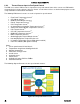
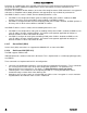
The following diagram illustrates the fan speed control structure.
Figure 26. Fan Speed Control Process