
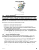
Intel Server Board S2400BB


Intel® Server Board S2400BB TPS
Revision 2.0
14
connection between two components. This supports traffic in both directions simultaneously. To facilitate
flexibility and longevity, the interconnect is defined as having five layers: Physical, Link, Routing, Transport, and
Protocol.
The Intel
®
QuickPath Interconnect includes a cache coherency protocol to keep the distributed memory and
caching structures coherent during system operation. It supports both low-latency source snooping and a
scalable home snoop behavior. The coherency protocol provides for direct cache-to-cache transfers for optimal
latency.
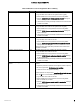
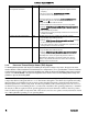
3.2.2 Integrated Memory Controller (IMC) and Memory Subsystem
Integrated into the processor is a memory controller. Each processor provides 3 DDR3 channels that support
the following:
• Unbuffered DDR3 and registered DDR3 DIMMs
• LR DIMM (Load Reduced DIMM) for buffered memory solutions demanding higher capacity
memory subsystems
• Independent channel mode or lockstep mode
• Data burst length of eight cycles for all memory organization modes
• Memory DDR3 data transfer rates of 800, 1066, 1333, and 1600 MT/s
• 64-bit wide channels plus 8-bits of ECC support for each channel
• DDR3 standard I/O Voltage of 1.5 V and DDR3 Low Voltage of 1.35 V
• 1-Gb, 2-Gb, and 4-Gb DDR3 DRAM technologies supported for these devices:
UDIMM DDR3 – SR x8 and x16 data widths, DR – x8 data width
RDIMM DDR3 – SR,DR, and QR – x4 and x8 data widths
LRDIMM DDR3 – QR – x4 and x8 data widths with direct map or with rank multiplication
• Up to 8 ranks supported per memory channel, 1, 2 or 4 ranks per DIMM
• Open with adaptive idle page close timer or closed page policy
• Per channel memory test and initialization engine can initialize DRAM to all logical zeros with
valid ECC (with or without data scrambler) or a predefined test pattern
• Isochronous access support for Quality of Service (QoS)
• Minimum memory configuration: independent channel support with 1 DIMM populated
• Integrated dual SMBus master controllers
• Command launch modes of 1n/2n
• RAS Support:
Rank Level Sparing and Device Tagging
Demand and Patrol Scrubbing
DRAM Single Device Data Correction (SDDC) for any single x4 or x8 DRAM device.
Independent channel mode supports x4 SDDC. x8 SDDC requires lockstep mode
Lockstep mode where channels 2 & 3 are operated in lockstep mode
Data scrambling with address to ease detection of write errors to an incorrect address.
Error reporting via Machine Check Architecture
Read Retry during CRC error handling checks by iMC
Channel mirroring within a socket
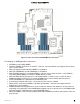
Figure 9. Memory Sub-system Functional Block Diagram